VA6AM Triplexer and Band Pass Filter Builds
The Concept
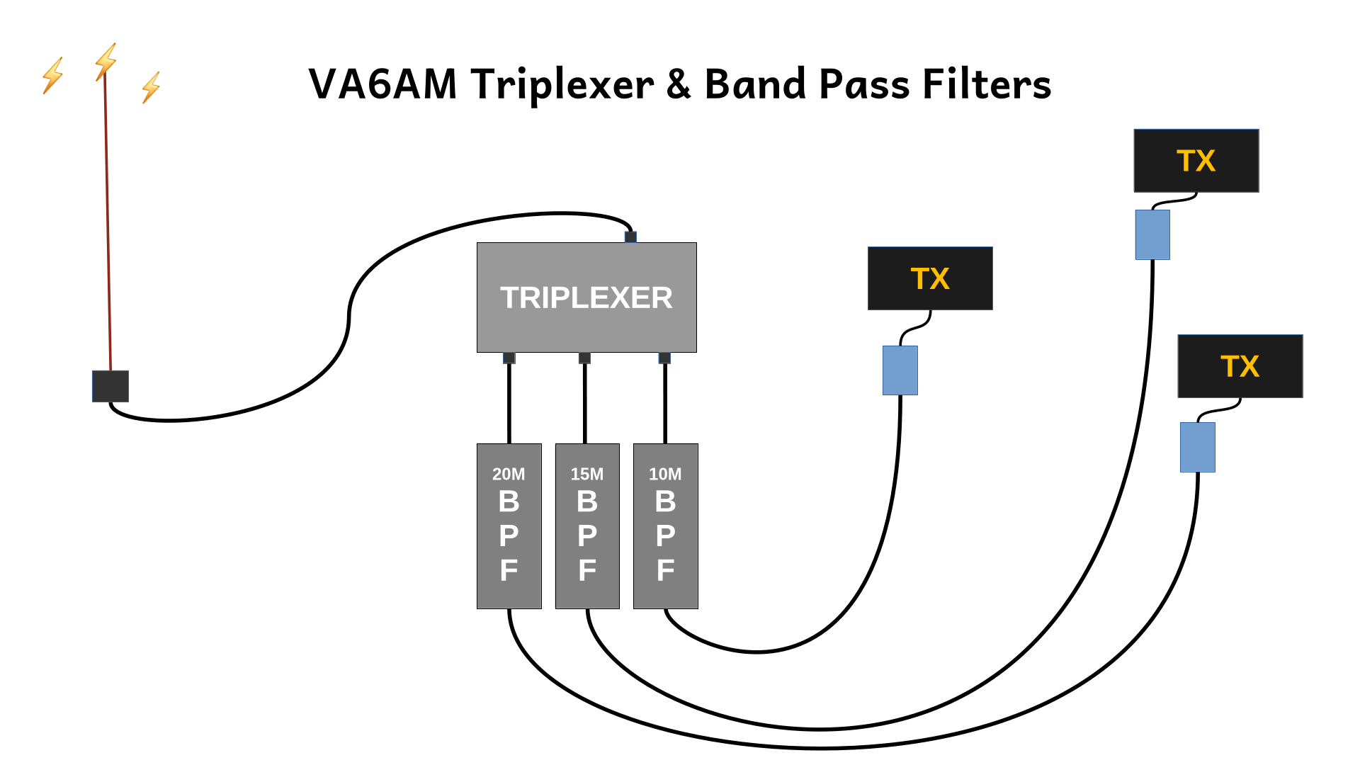
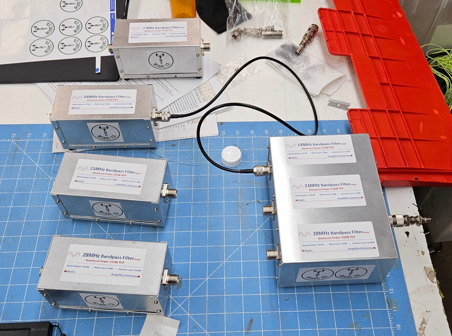
Ham Radio Field Day can be a rip roarin’ good time for individuals and clubs alike. If you are operating as a club or with more than one station, you need to have equipment that will keep your transmissions from interacting with adjacent stations. This is where Band Pass Filters come in. And, as an added bonus, you can run multiple stations on the same antenna with the magical Triplexer. Our club elected to buy a kit of band pass filters for 10M, 15M and 20M as well as the accompanying Triplexer. We built them and used them at Winter Field Day. They worked so incredibly well that we elected to purchase the low band versions as well. We just completed building the 160M & 80M filters (we bought the 40M filter with initial set) and the Low Band Triplexer. This post is some notes about the overall build process and experience. This should not be understood as a how-to guide or manual.
VA6AM
Pavel, VA6AM is the creator and mastermind of the kits. His website is VA6AM.com where you can find all the products he has available. The kits we bought were the low power 100W versions. But he makes high power versions too.
What You Get
The kits come with all the parts you need. The website has the parts lists and we recommend printing them off so you have the reference material handy for the build process. Pavel includes build instructions for each filter and triplexer when you purchase. Our critiques is that they could have been a bit clearer. We were complete novices coming in to the build process and none of us are engineers. So we found it a bit tricky at times to know what to do. I think this is an industry standard type thing though. Super smart engineers should not write instruction manuals for normal people LOL.
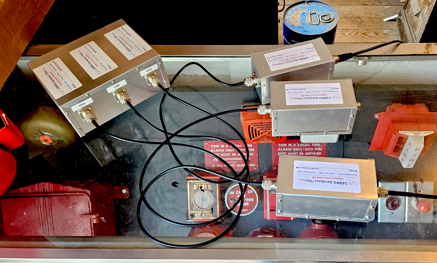
Band Pass Filters
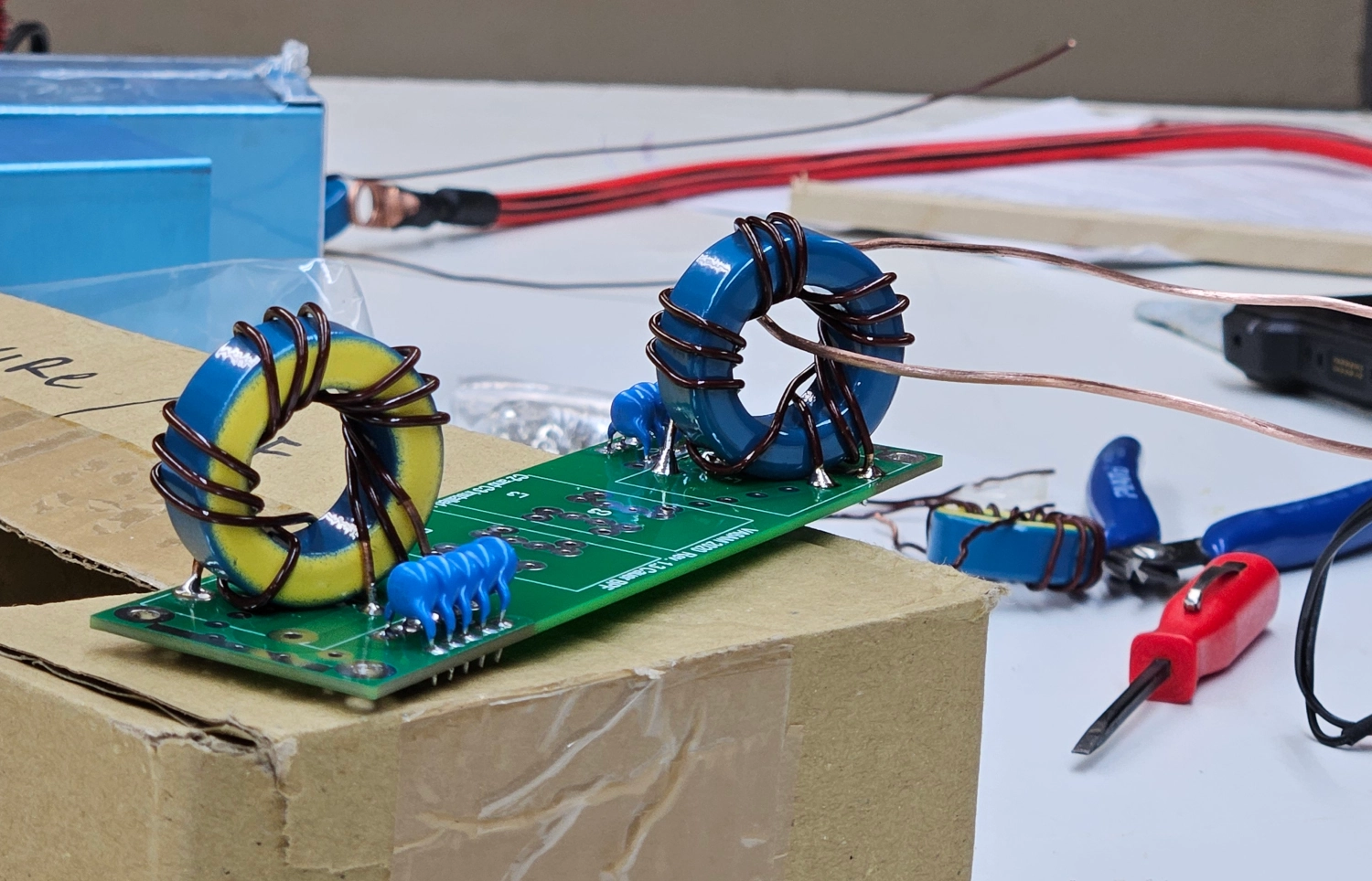
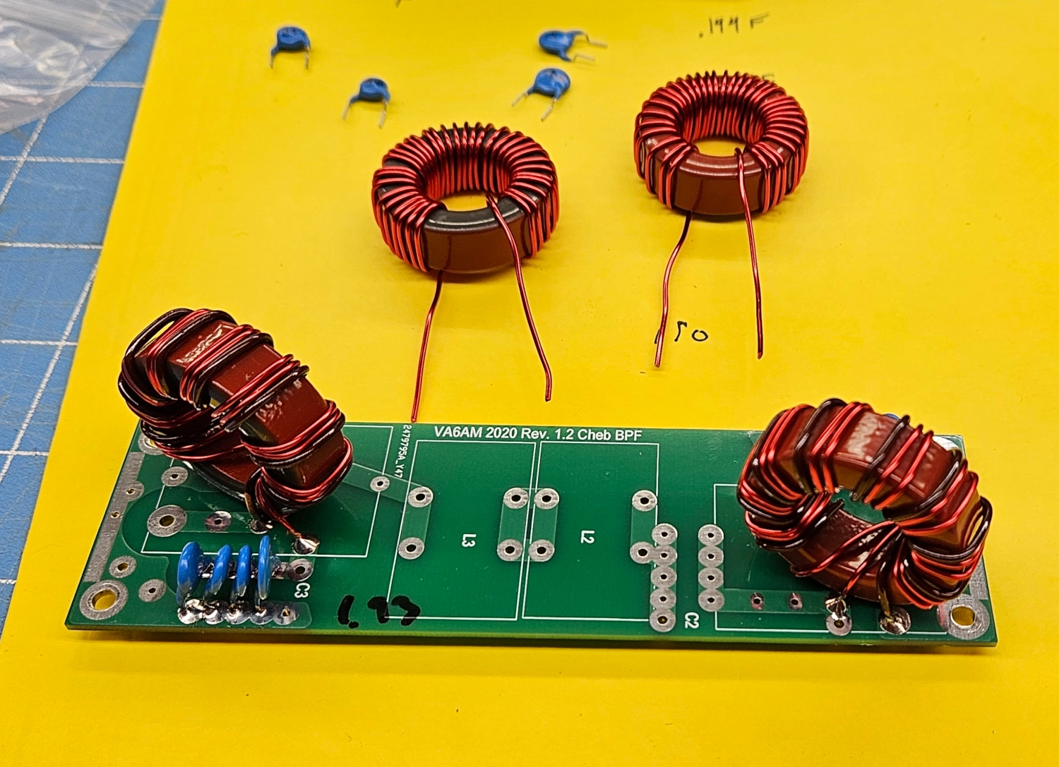
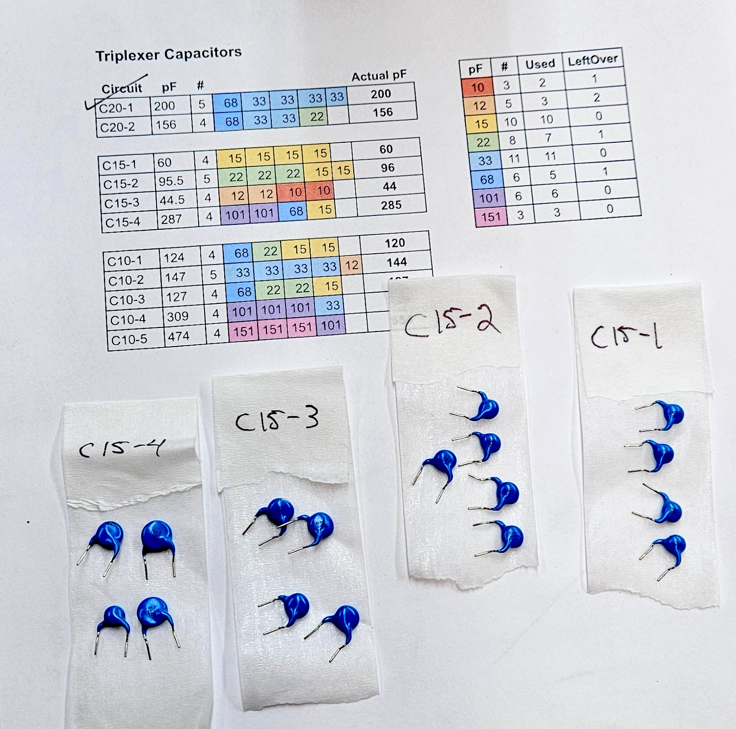
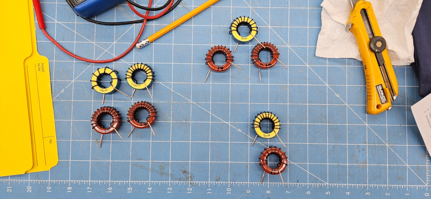
Each filter comes as a circuit board with the end inductors and capactors pre-soldered in. We found them to be well tuned and didn’t really require any adjustments. As per Pavel’s instructions, you fit the board into the enclosure to install the standoffs and then you proceed to build the two center circuits. The instructions give the specs for the required capacitors and inductors. We measured and labelled all of the included capacitors with an LCR meter. You solder the capacitors first which go on the bottom of the board.
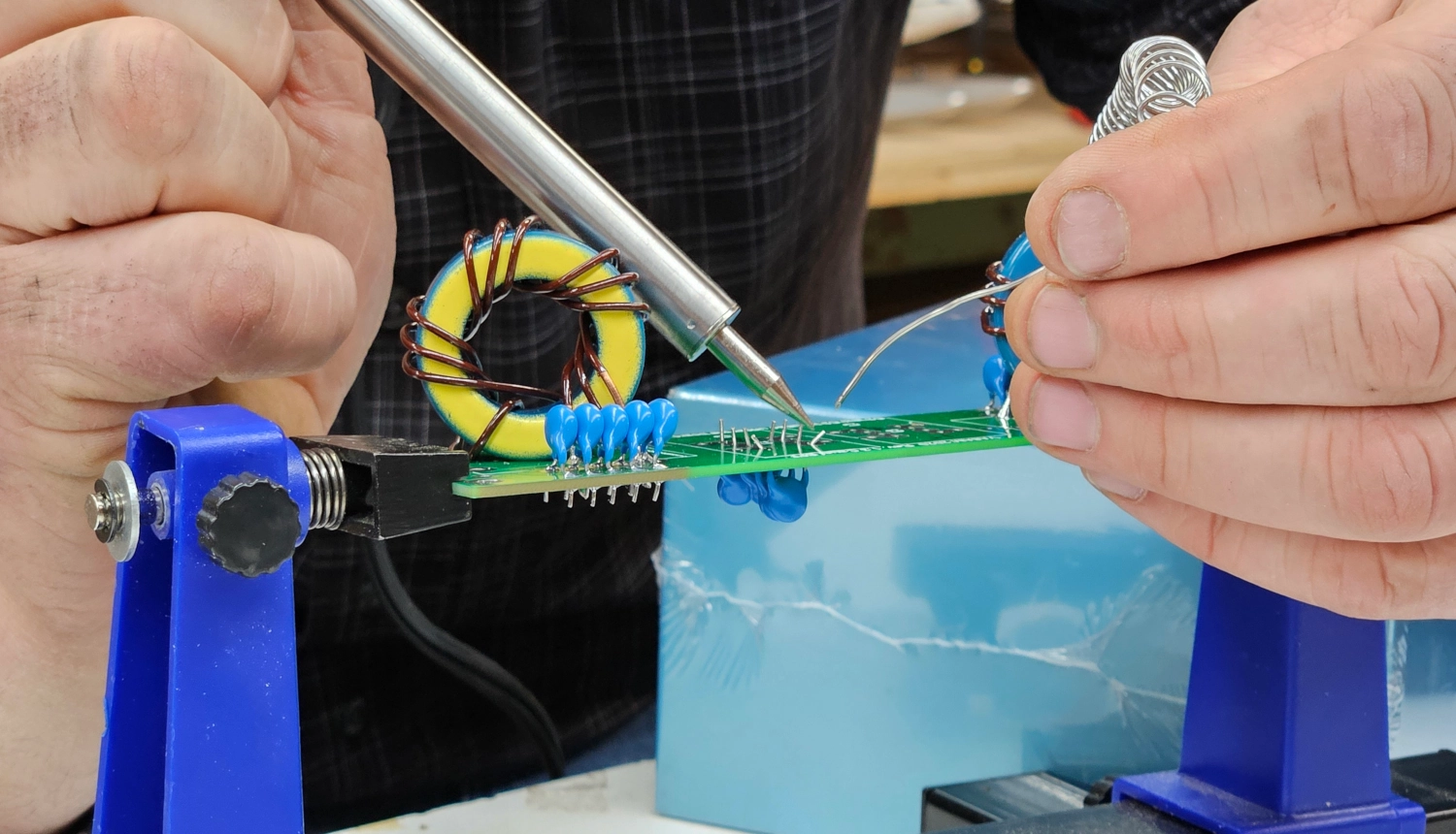
You then move on to the inductors and solder them in. Depending on the band, the directions specified a little insulating barrier to go under these cores. We used teflon baking sheet material for this.
Here’s the initial setup for the 160M filter:
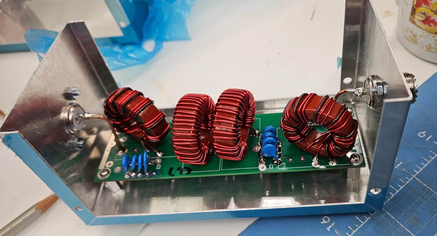
And here it is assembled in the enclosure:
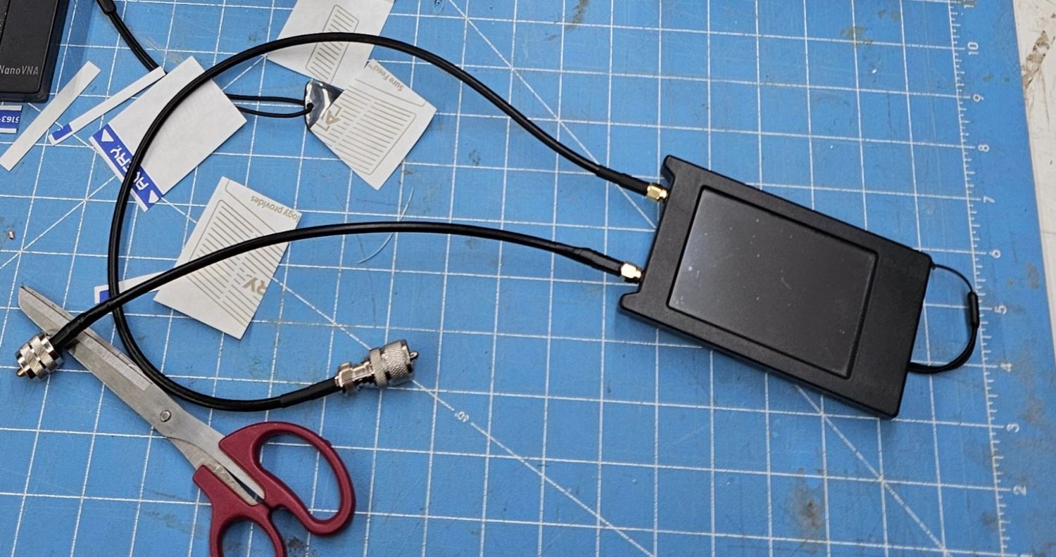
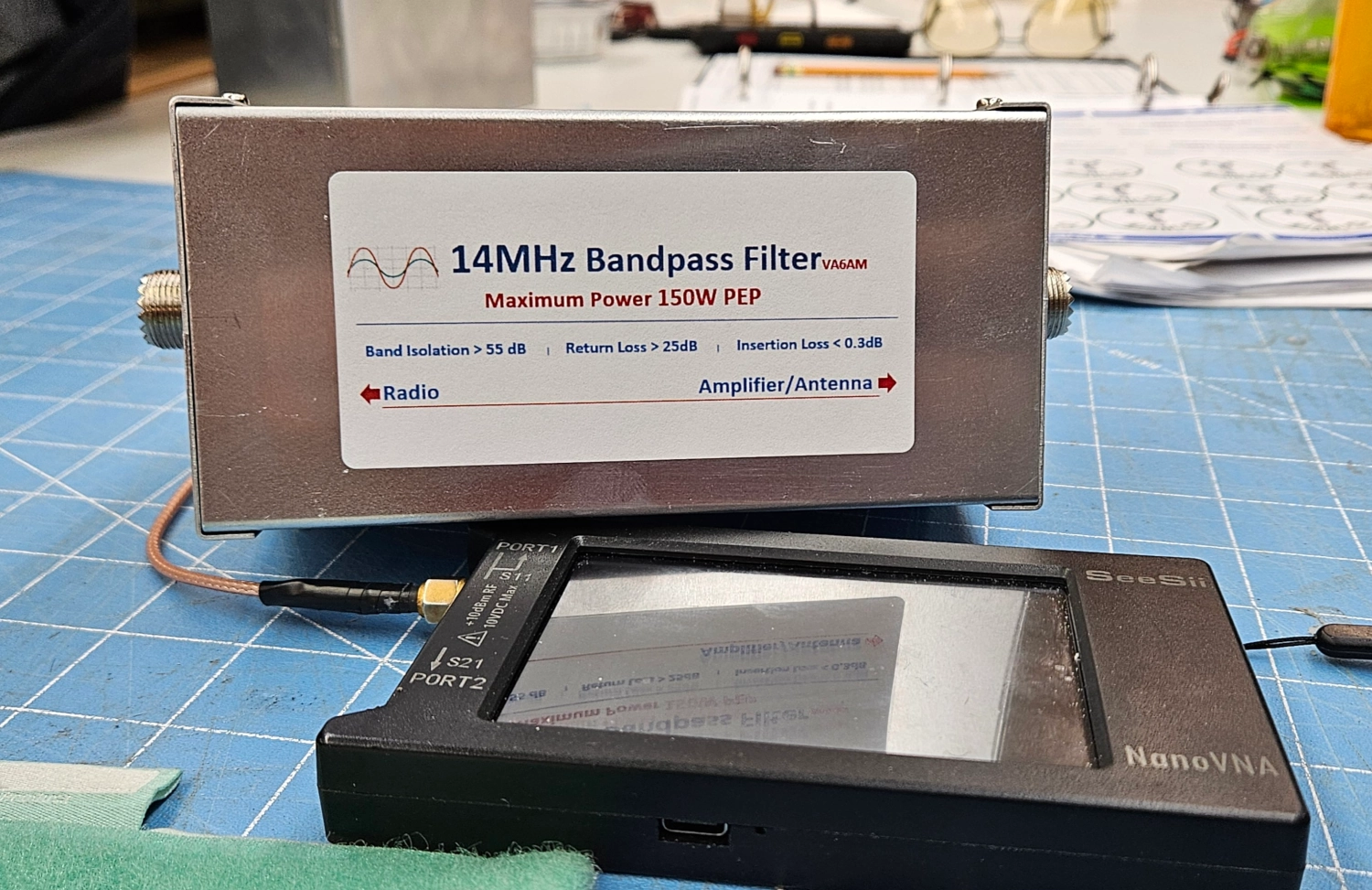
NanoVNA Setup
To test and tune the filters, we used a NanoVNA. Essentially you are testing for two things: SWR and LogMag. The SWR will indicate how well tuned the filter is for your desired frequency and the LogMag will show how much attenuation you get on either side of that frequency. You want to absolutely curb stomp adjacent band signals so you don’t interact with others around you. We used two SDA to PL-259 leeds to hook up to the filter.
Here’s how to setup the Nano step by step:
1. MAIN MENU → STIMULUS
- Set stimulus for just above and below your intended frequency. Ex: 6M and 8M if measuring 7M/40m Band.
- ← Back
2. MAIN MENU → DISPLAY → TRACE → TRACE 0
- ←Back, FORMAT S21 (THRU)→ LOGMAG
- ←Back, CHANNEL S21 (THRU)
- ←Back
3. MAIN MENU → MARKER → SELECT MARKER → choose MARKER 1 2 3
- These markers will be for the low, desired and high frequencies
- ← Back
4. MAIN MENU → CALIBRATE → CALIBRATE → choose OPEN, SHORT, LOAD, THRU, DONE
Setup with any cables/adapters you need to measure the filter then do the calibration
←Back
5. MAIN MENU → DISPLAY → SCALE → SCALE/DIV → 5 enter
This setting makes the data easier to see
←Back
6. MAIN MENU → MARKER → SELECT MARKER → MARKER 2
This selects the desired frequency marker
←Back, SEARCH MAXIMUM, ←Back to dismiss menu
This shows frequency and insertion loss
Proceed to dragging Marker 1 and 3 as close as possible to -3.06db right and left of Marker 2’s frequency.
These markers will illustrate the high and low cutoff frequencies for the desired band and also measure if you are accurate to your desired frequency.
If Marker 2 is off of your desired frequency, adjust the filter components to get on frequency
Video for further information.
Making Adjustments
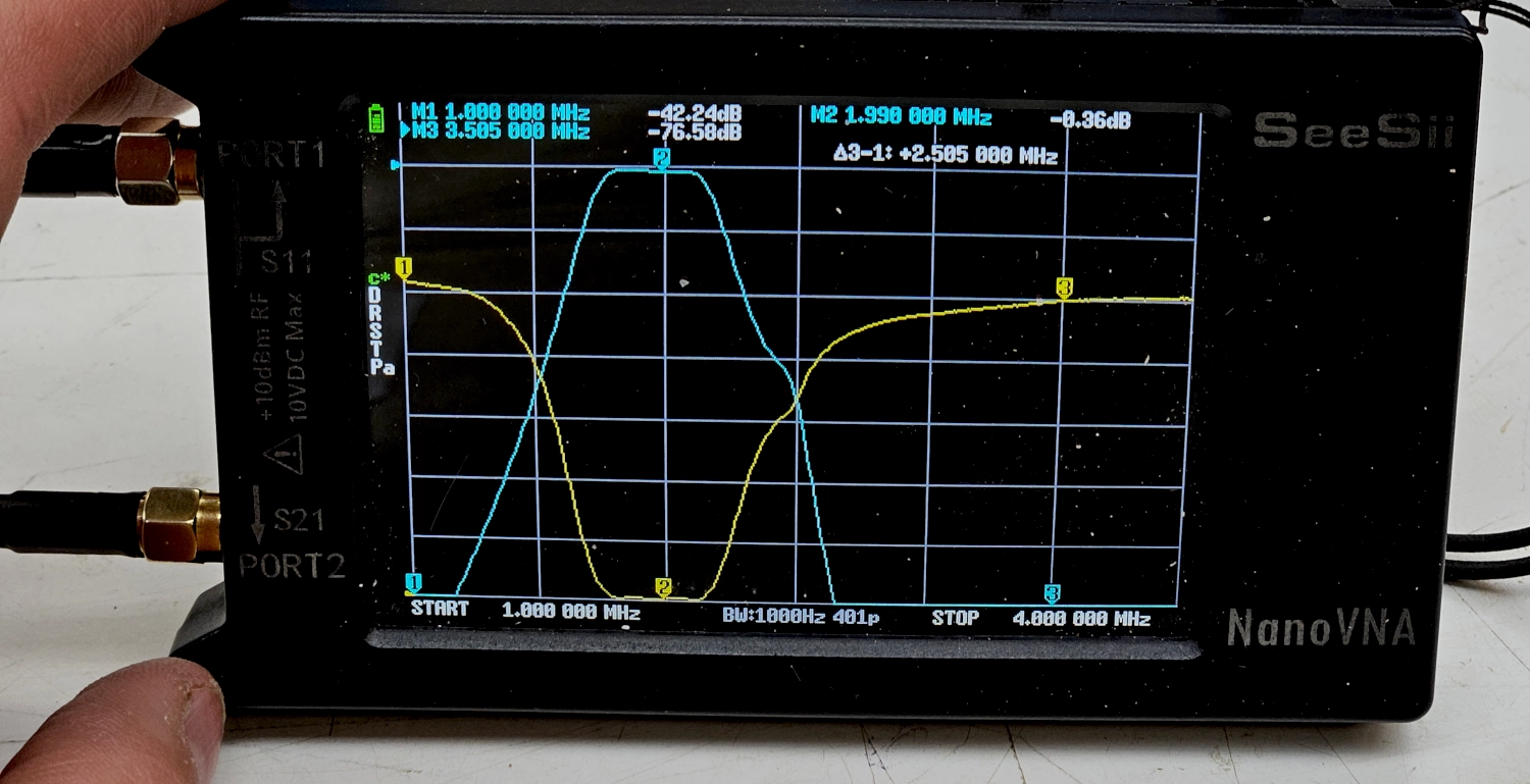
This is what the Nano should look like when measuring a filter:
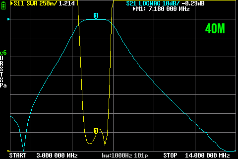
The blue trace is the LogMag showing the attenuation on either side of the passing frequency and the yellow trace is the SWR, showing how well tuned the circuits are for that passing frequency.
If we zoom right in on the band itself, you can see how well we did with the tuning process:
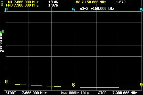
In this case, not too shabby. The worst is 1:146 SWR. You adjust this by either compressing or spacing the windings of the inductors. What we found useful for this was a plastic autobody tool for removing car trim. But any kind of plastic thing will work. You need to be careful not to remove any of the enamel from the wire on the toroids. So the plastic is the ticket to not scratch anything but you can still apply a good deal of force if need be. This part of the process can be finicky, but you basically keep compressing and expanding the windings until the Nano shows good/flat SWR. Then put the cover on the box and make sure it’s hasn’t changed. We found this didn’t really affect our tuning at all.
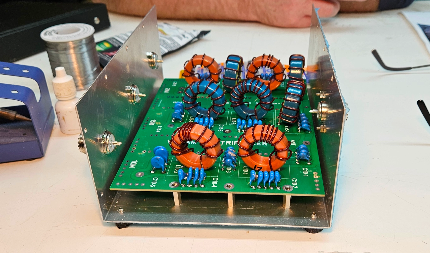
Enclosure
Once you are happy with the filter, you close up the enclosure. We added labels that Pavel has on the website. We bought 4”x2” labels for this. Using LibreOffice Impress, I laid out the labels on a Letter sized sheet and did a test print to make sure the labels lined up. Using the Nano, one side of the filter will be better performing than the other. The best performing side of the filter should go towards the radio - hence the sticker direction.
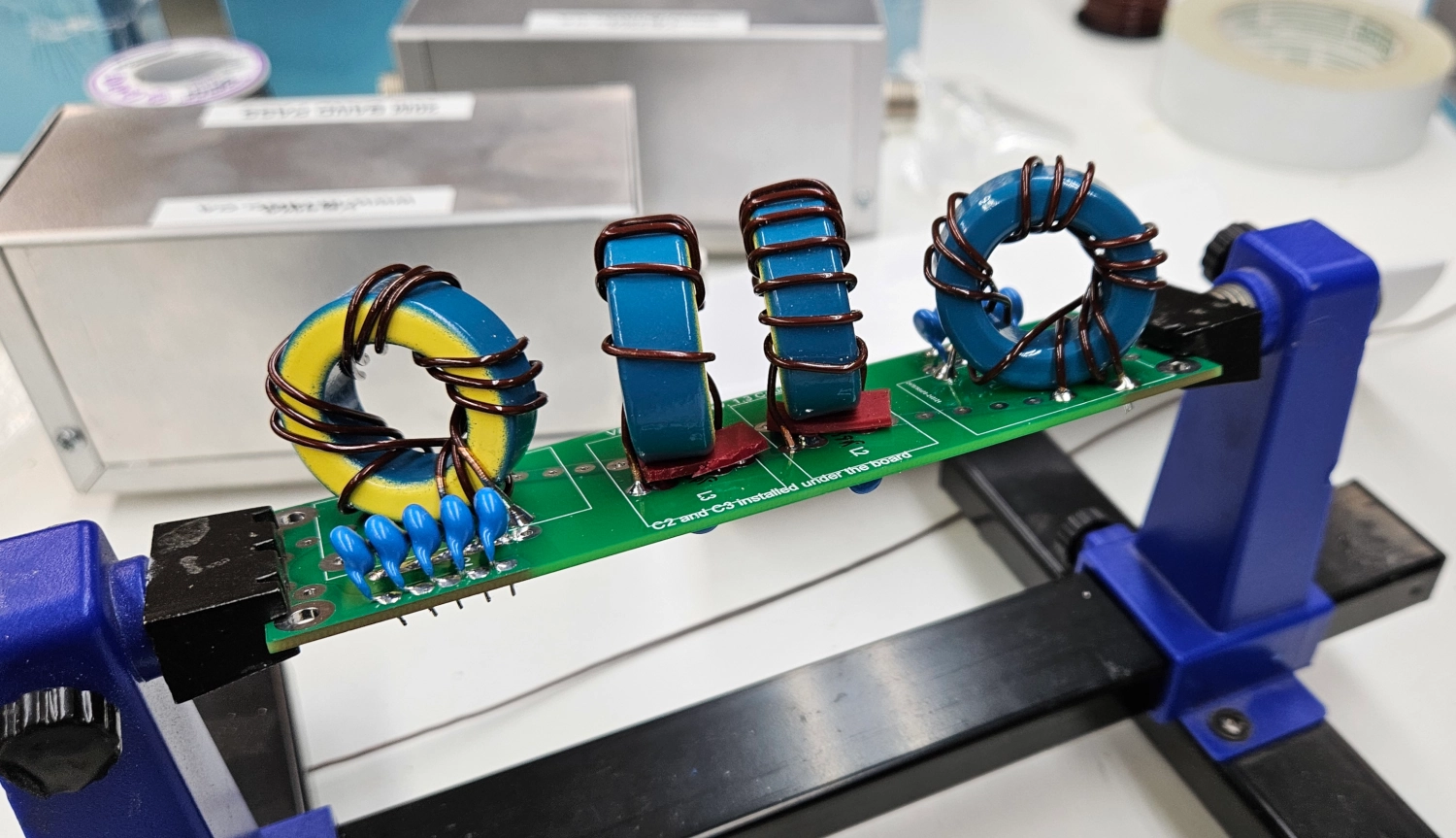
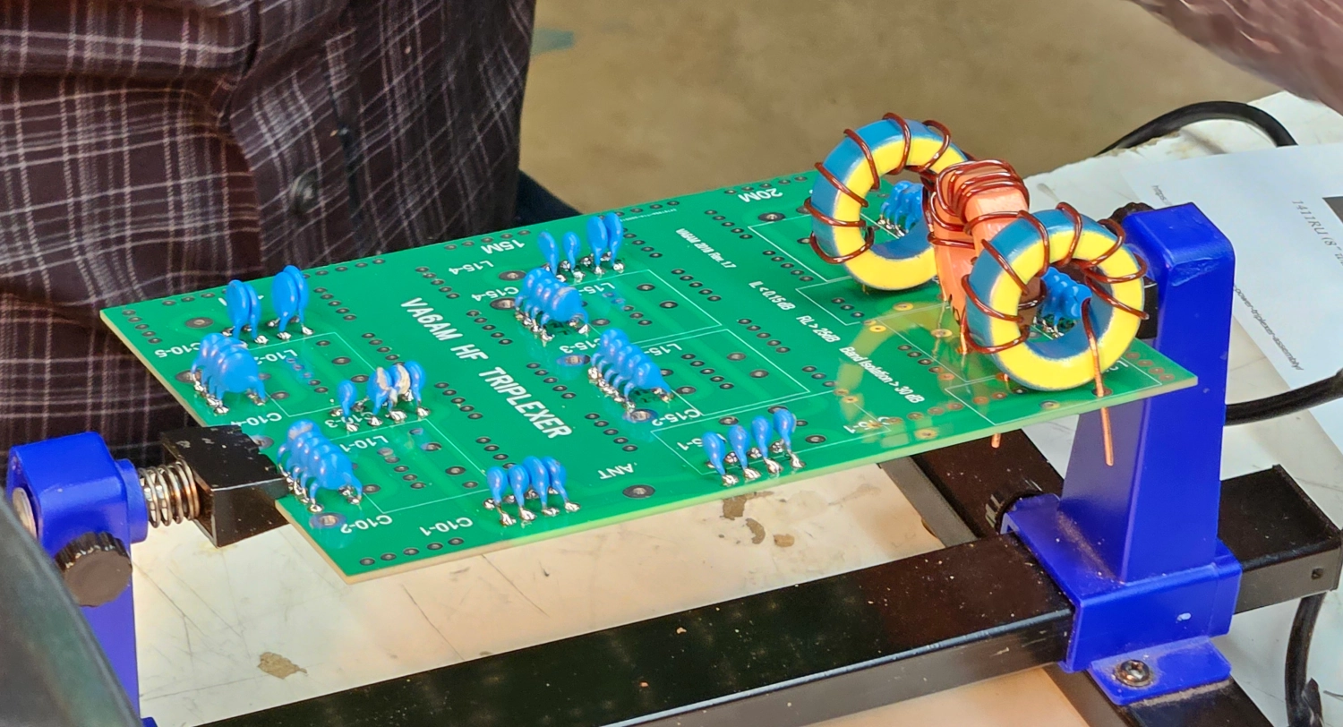
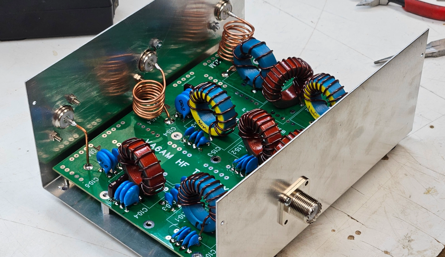
Triplexer Notes
So the Triplexer is basically just three band pass filters combined into one. It follows much the same procedure as the filter builds, but it doesn’t come with anything pre-installed. This had us freaking out originally. But after you get the hang of the filter builds, the triplexer is actually pretty simple. Worthy of note: both the low-band and high-band triplexer use the same circuit board. This confused us at first. But you can just relabel the low-band bands on the board with a marker or a label maker.
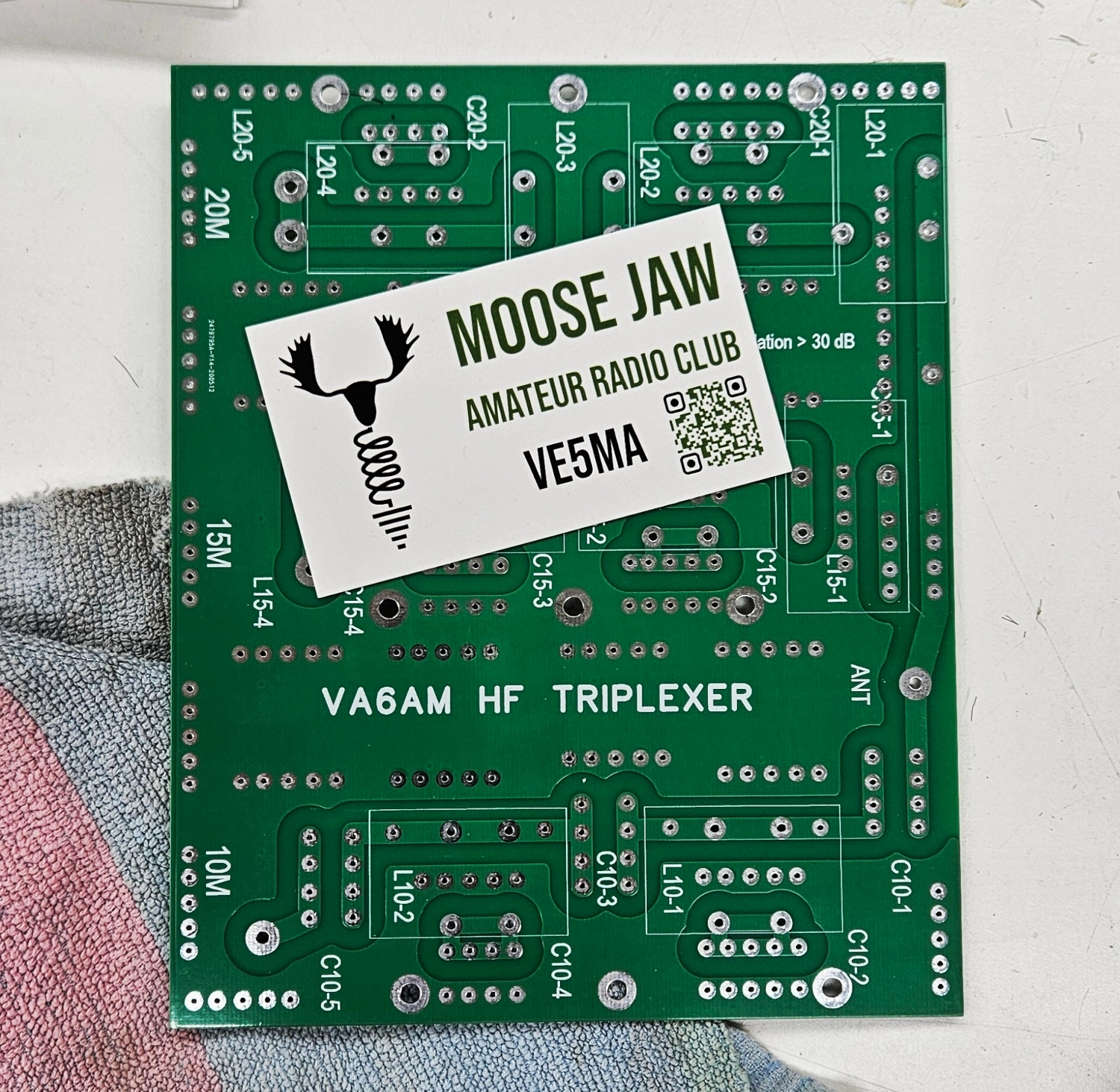
Lay Out the Components
Just like Ikea furniture, we laid out all the components. We measured and labelled all the capacitors just as with the filters. We placed the capacitors by circuit onto some masking tape to keep them from getting mixed up. For the low band version we found that we had one inductor that was short one winding and so we had to rewind one of the cores which was no biggy.
Avengers, Assemble!
Then, as per the filters, solder away! We installed the capacitors first and then moved on to the inductors.
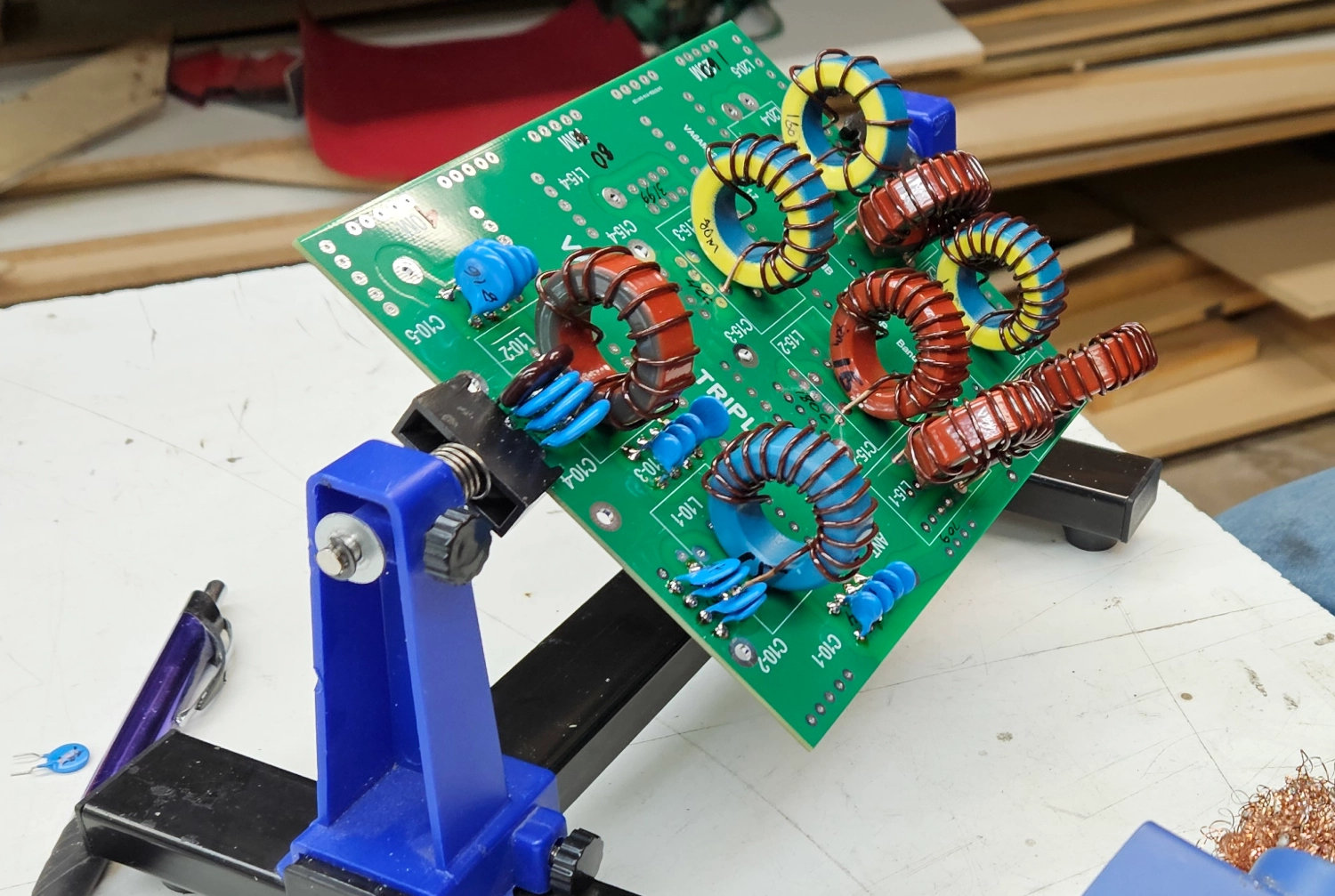
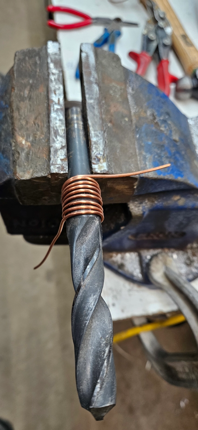
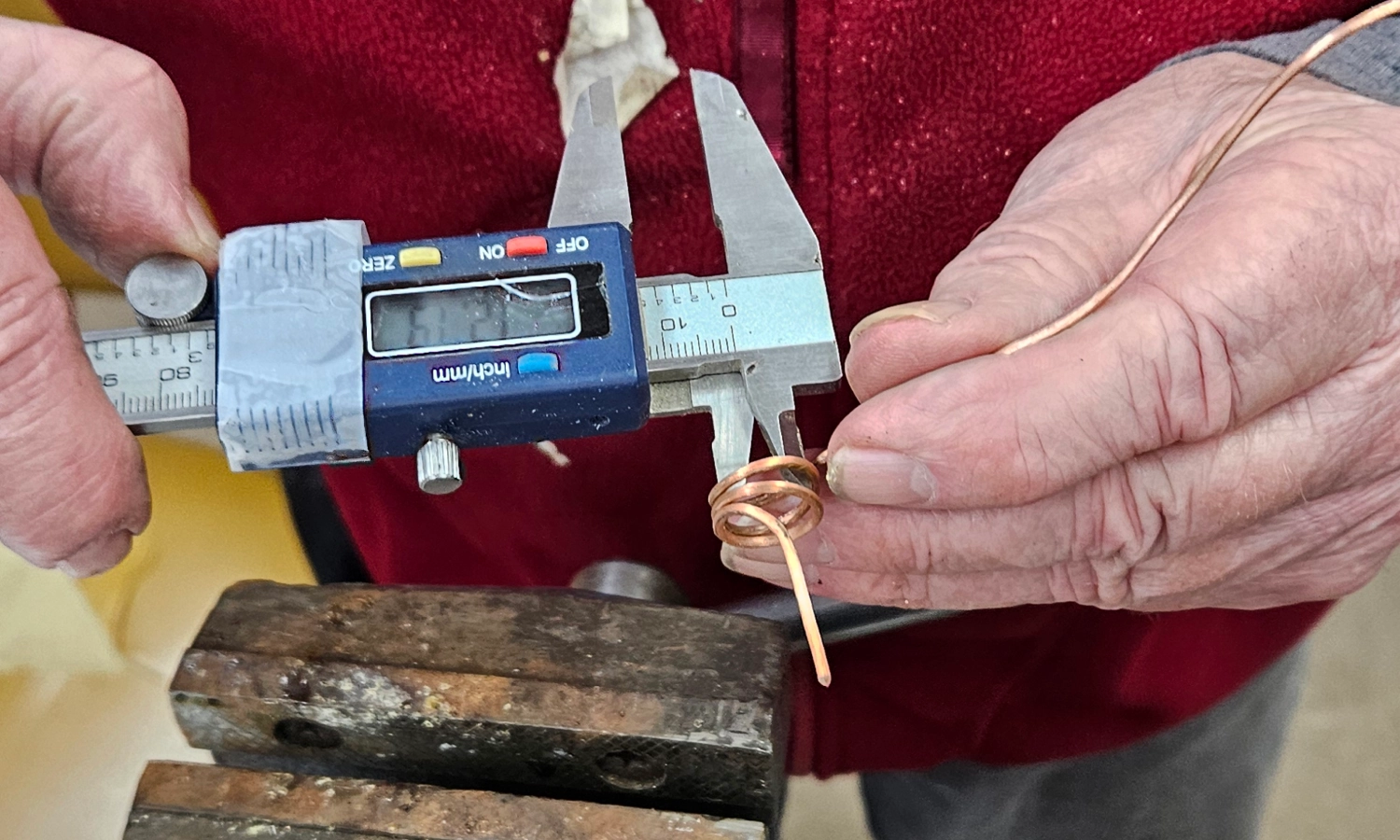
Air Coils
The directions spec air coils that you need to make from scratch. Again this is no biggy. We used a drill bit as the former and just wrapped it with copper wire. Measuring with a caliper you can make sure its to Pavel’s specs. These are what connect the circuit board to the SO-239 connectors in the enclosure. Otherwise you just connect with a piece of copper wire as in the 40M shown below.
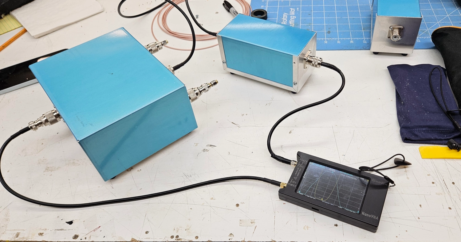
Final Testing
Lastly, you hook up your Band Pass Filters one at a time and check the performance. You need to use 50 Ohm loads on all the unused ports.
This Nano reading wasn’t final, but it’s the only picture I have. This was our 160M filter and triplexer. You can see that we have -42dB on the 1MHz side and -76dB on the 3.5MHz side. The final results were better, around -75dB on each side of each band. That’s killer attenuation!
We built these to use a short jumper wire between the filters and the triplexer. But the Chad thing to do would have been to make sure the filters and triplexer were precisely lined up. You could then use a male-to-male PL-259 connector and skip the jumper. But this build gives a bit of flexibility.
Setup for Field Day
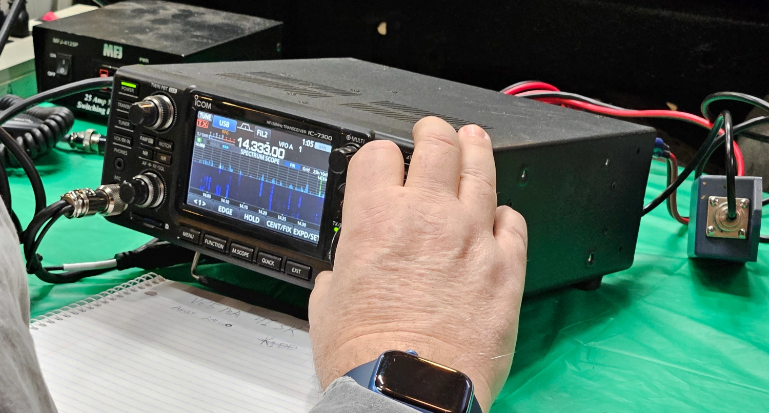
As mentioned in the outset of this post, this equipment performed amazingly well. We only had 1 hiccup and that was failing to install 1:1 chokes at the rigs. The coax runs were acting like antennas and were picking up signals rig side of the triplexer and band pass filters. We realized this and installed 1:1 chokes at each rig and voila! Problem solved. We ran the triplexer into a Yagi and had 10M, 15M and 20M stations running on that same antenna. For the 40M station we setup a separate G5RV antenna. It was so great to have 4 stations operating at the same time in the same room on Field Day! In the past we might have had maybe 2 stations. This allowed us to get more contacts than ever before.
We are looking forward to this summer’s Field Day where we can deploy the low-band setup for night contacts!
73 de VE5REV