Toggle Switch EFHW -- FAILURE
UPDATE
After more field testing, this build was an abject failure! The toggle switch is too close together and I believe the wires capacitively couple together. You can’t adjust the wire legs independently of each other due to this. You can dial in 40M close but then the 20M section gets whacky. So it is back to the drawing board on this idea! Post is left up for posterity.
When I got my first EFHW transformer from TennTennas, I was totally stoked! 40M, 20M, 15M and 10M with resonant harmonics! 4 bands in one with no tuner needed! It was so great! But then I realized that the convenience trade off came at a loss in efficiency. And also, the radiation pattern of the antenna goes wonky when you transmit on harmonics. Maybe there was a better way?

The Concept
They’ve had linked EFHW and linked dipoles for quite some time. It’s a reasonable, light and easy solution to the problems mentioned above. Resonant band switching via connectors. The problem I personally have with said connectors is that I break them, like almost all the time. Even if I crimp, solder and glue-shrink wrap the connections, I always end up wrecking them. Then you’ve got a broken fiasco in the field. I started to think about a switching system as an alternative way to accomplish the same goals.
The Build
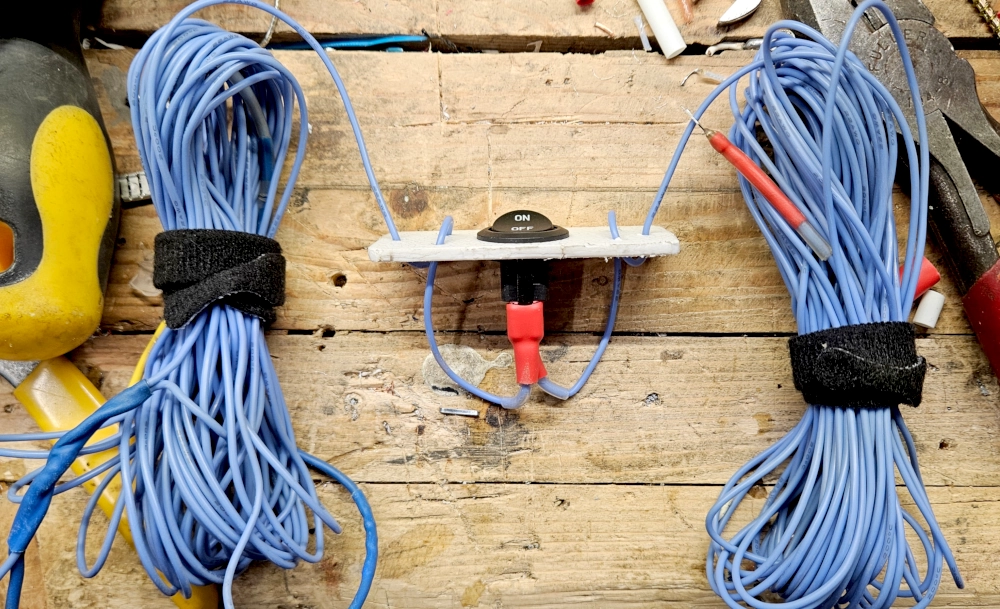
Toggles
The toggle switches are just Amazon cheapies. I tested them for continuity to make sure the switch worked. I took some cheap cutting board from the dollar store and made a mounting plate for the switch with holes for strain relief. I used a step-bit to drill out the toggle hole in the middle. If this project is viable, I’ll work up some 3D printed mounting plates.


Wire
I had some 22 AWG silicone wire from BNTECH go that I had previously used for a 40M EFHW. I cut it in half and installed some female spade connectors. I crimped and soldered and double glue-shrink wrapped them for spite.

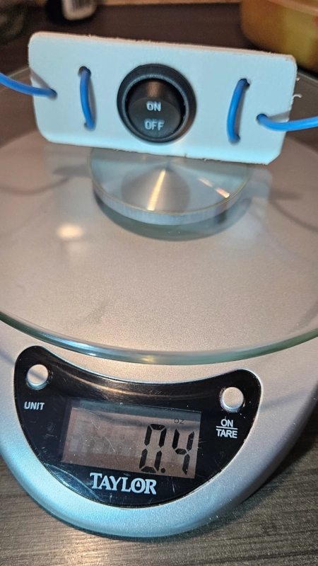
Weight
I had wondered how this was going to be with the extra weight and bulk of the switch and cutting board. However, they’re pretty darn light at only 0.4oz or 11g per switch.
Deployment
I envisioned this setup as a sloper. For the initial setup I deployed the DX Commander mast on the backside of the city water pump house. It has a pretty sharp drop off and a fence that I ball-bungeed the mast to. I went down to a plastic electric fence picket for the transformer.

Transformer
I used my 56:1 with 3’ of unchoked coax as counterpoise. Then I had the 1:1 choke and 25’ of coax. Normally when I use the 40M band it does better with a little extra inductance over a 49:1. However, I think this was actually too much for this deployment based on my NanoVNA field data.
Field Testing
These are the initial readings with the first deployment. Manually flipping the switch was super easy.
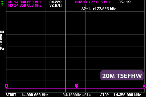
20M
Resistance:
You can see right off the hop that there’s too much transformation with the 56:1. It’s got the impedance too low at ~33Ω.
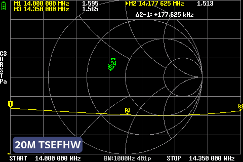
SWR:
And as predicted you can see the SWR creep because of that transformer mismatch.
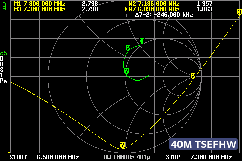
40M
Resistance:
Even on the 40M the impedance was a bit low.
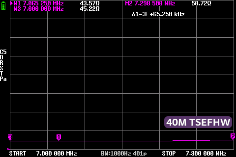
SWR:
There’s some wild inductive reactance happening on 40M. The resonant point was too low, meaning it needs to be trimmed a bit on the 40M segment too.
Next Steps
I think I will retry this deployment with a 49:1 transformer and see how that goes. It might be the ticket for a better match with this antenna deployed as a sloper. But for ease of band switching, this design is super snazzy. You don’t have to fiddle with anything or risk breaking connections or having them come apart unintentionally with the toggle switches. It was insanely windy when I did this deployment and everything was bouncing around quite a bit. But it held up nicely and remained solid even under substantial stress.
73 de VE5REV