Transmission Line Transformers
I came across the concept of Transmission Line Transformers (TLT). I hadn’t previously heard about them but there is an opus on the topic by silent key Jerry Sevick. I struggled really hard trying to figure out the difference between these and typical transformers like Voltage/Current Ruthroff/Guanella. These are just some notes on the topic.
Video Resources:
Concept
Traditional transformers transfer energy via magnetic flux. The primary coil generates a changing magnetic field when an alternating current flows through it. This magnetic flux links to the secondary coil through the transformer’s core, inducing a voltage and transferring energy to the secondary circuit. The core, typically made of iron or ferrite, enhances the magnetic coupling.
Due to physical imperfections of any build, some inductance doesn’t contribute to the coupling and is referred to as Leakage Inductance.
Also, the wire windings create Inter-winding Capacitance. Inter: between turns of different wires. Intra: between turns in the same wire.
If the transformer is rotated 90 degrees, these two deficiencies of traditional transformers combine together to and act as a Characteristic Impedance.
Leakage Inductance + Inter-winding Capacitance = Characteristic Impedance (much like coax or a transmission line).
Differences
Traditional transformers are all about the number of turns through a toroid in the primary/secondary ratio (Ex: 49:1). TLTs do not do this. They use bifilar/trifilar/quad(etc) runs of wire.
Signals pass through the conductors from source to load with no DC isolation/no magnetic flux hand off like a traditional transformer.
The same ferrite cores are used, but they function differently, stabilizing transmission line operation, increasing low frequency separation between input and output
TLTs have performance gains of lower insertion losses and wider bandwidth
Important Detail
Input energy is sent down the transmission line as an electromagnetic field, completely contained in the transmission line. Placing a magnetic core around that transmission line will have no effect on the field inside the line (coax).
However, as the transmission length becomes less than 0.1 wavelength, the field is no longer contained within the line so both conductors contribute magnetic flux in a core around the line. This external flux converts the line and core combination from a transmission line into a conventional transformer.
If the transmission length is greater, then it doesn’t function this way!
At 3.5MHz 0.1L is 8.75m/29’. At 30MHz 0.1L is 1m/36”.
This property kicks in more significantly with higher frequencies as that length becomes physically shorter (1090MHz L > 2.75cm).
For HF, Transmission Line Transformers basically never operate as transmission lines. They instead operate as conventional transformers but with different wiring configurations which give better performance. In practice, it is essentially a hybrid of the two.
Conventional Transformers Examples
- What impedance are you trying to match? 50:200, 50:450, 50:2450, etc.
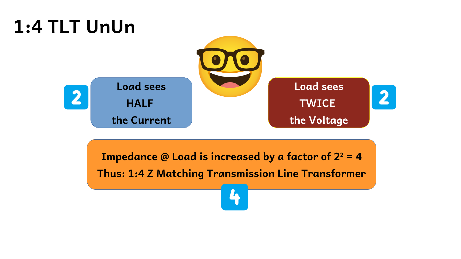
Z Match Ratio
- Z Match = 200/50 = 4
Turns Ratio
- Turns Ratio = Square Root of Z Match Ratio
Core
Visit toroids.info
Select your core of choice
Input the MHZ and the desired ohm match, click calc.
It will tell you how many turns you need. Round up.
This becomes the turns ratio
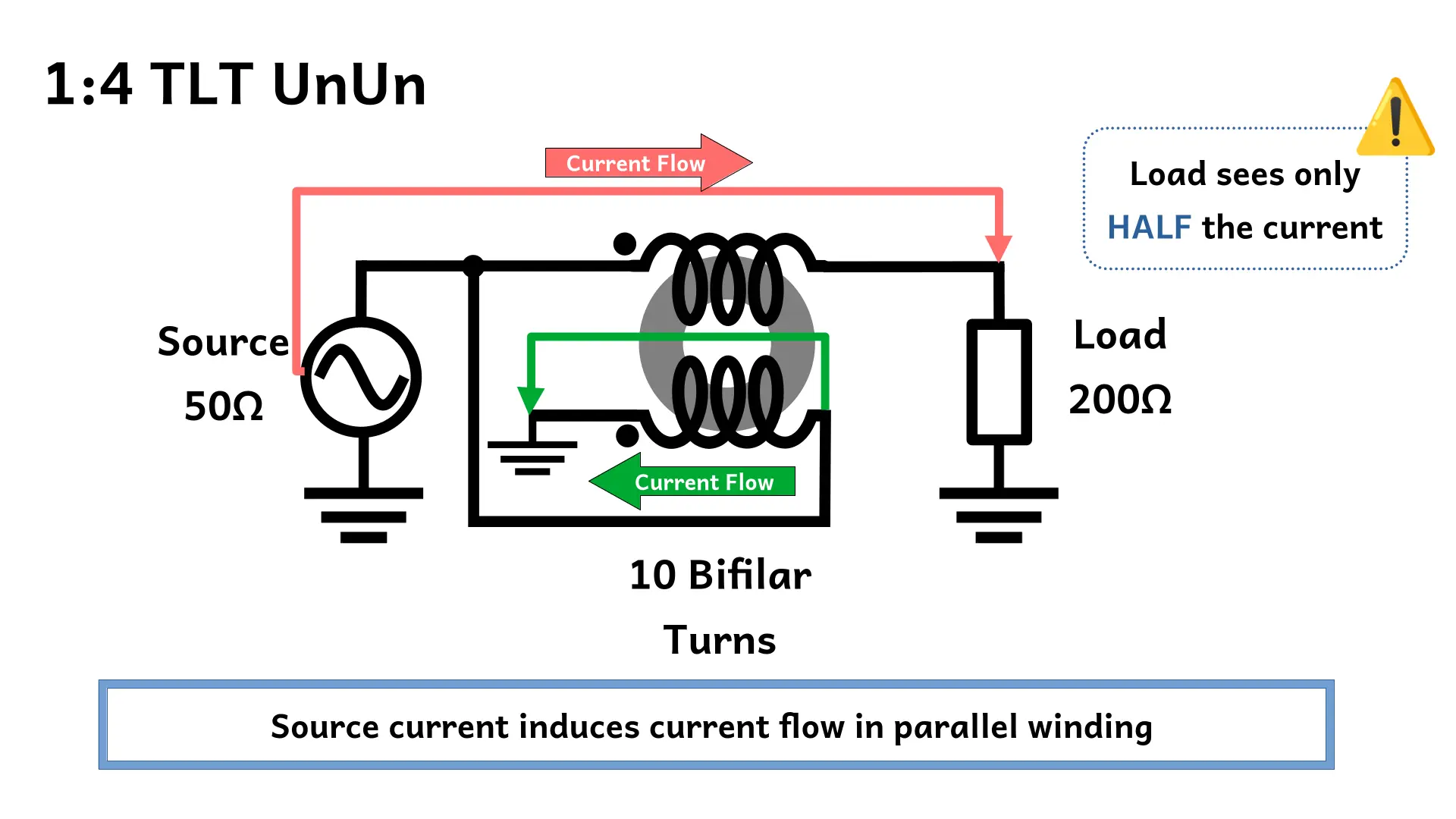
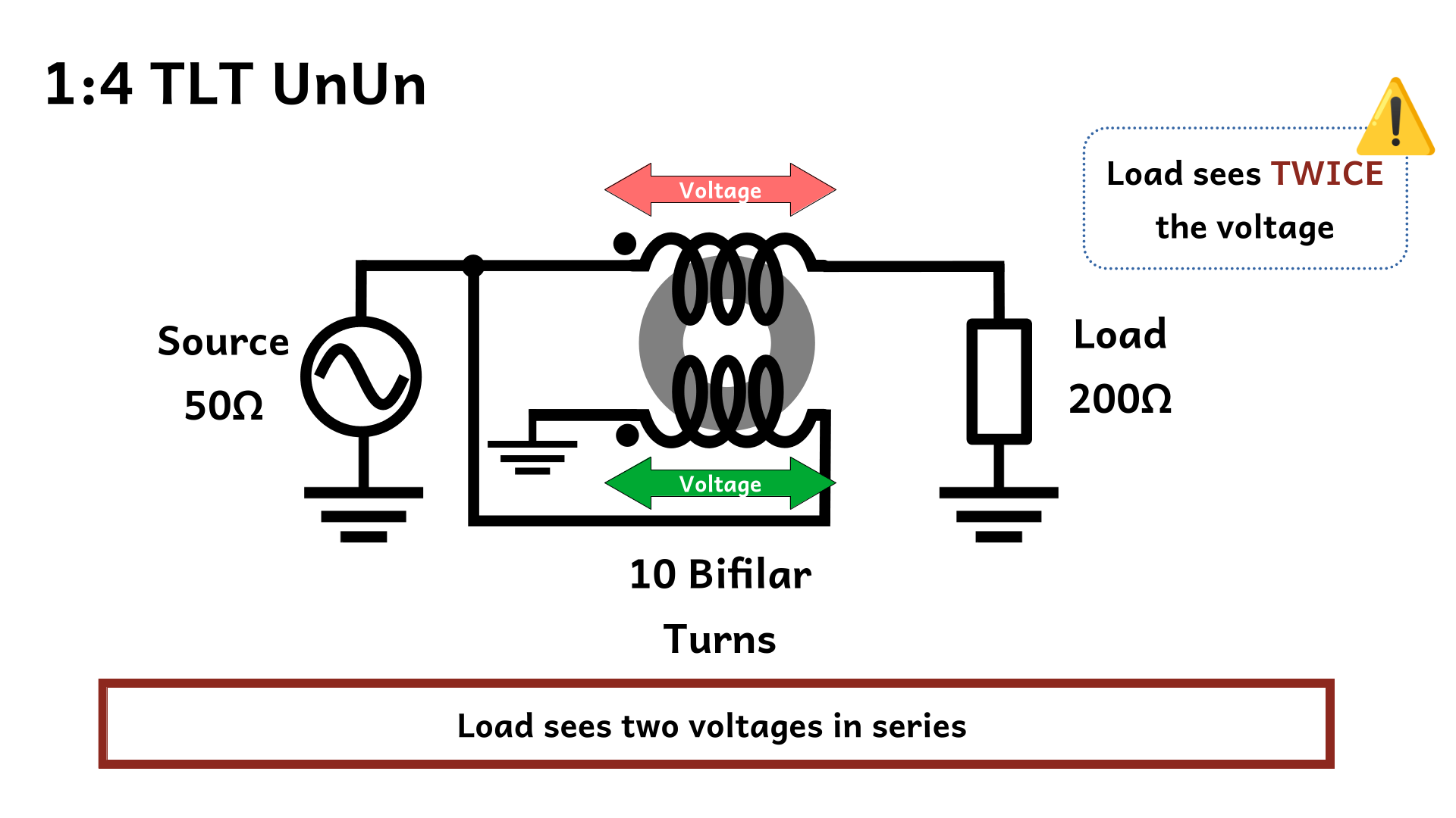
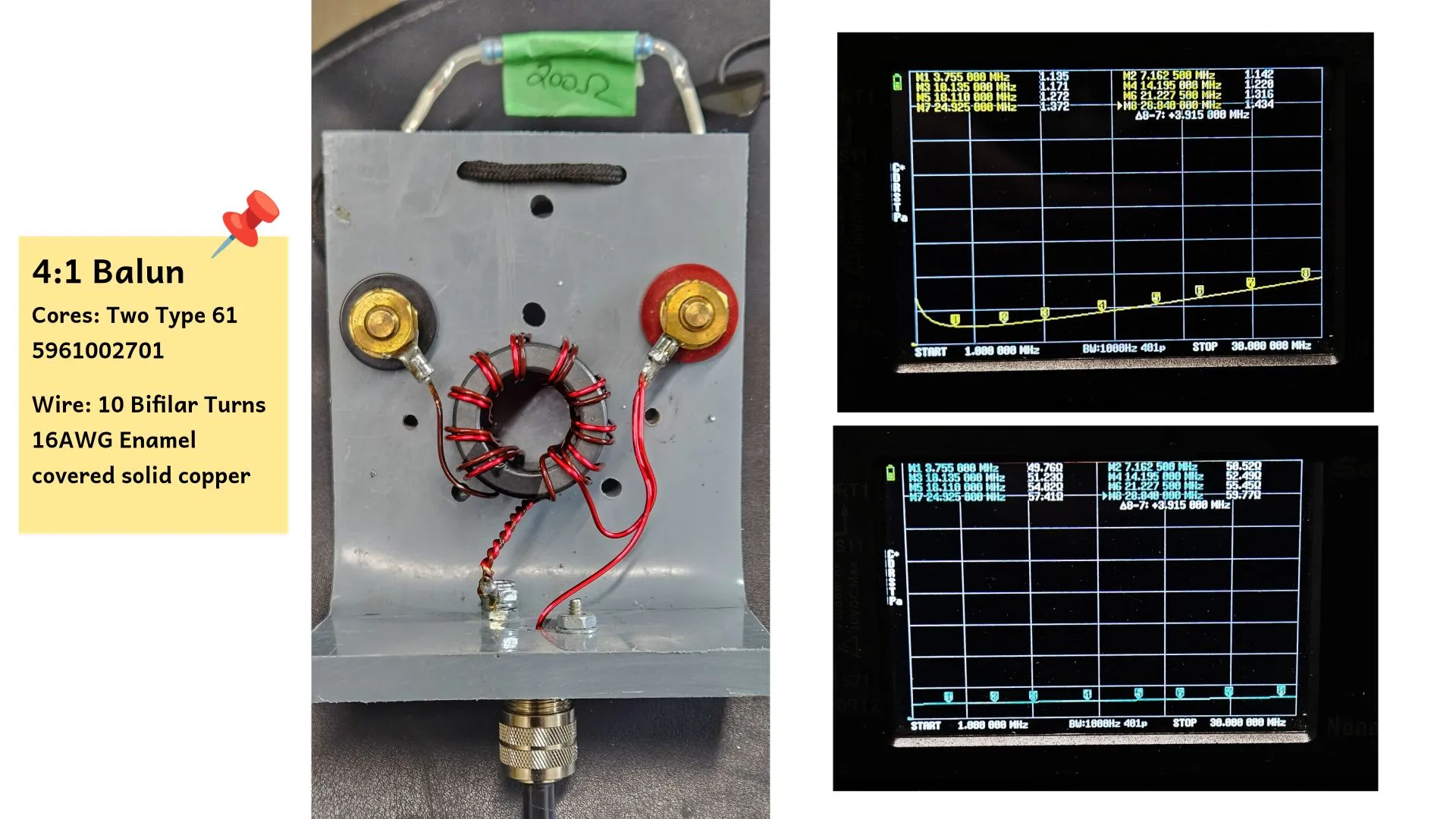
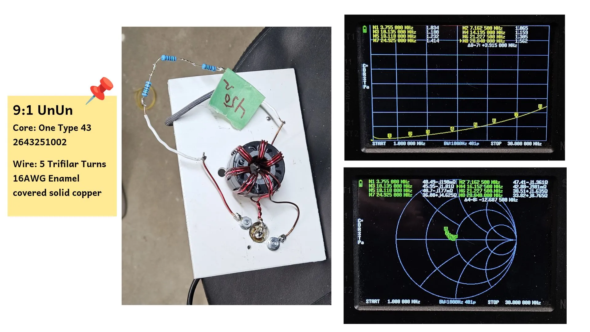
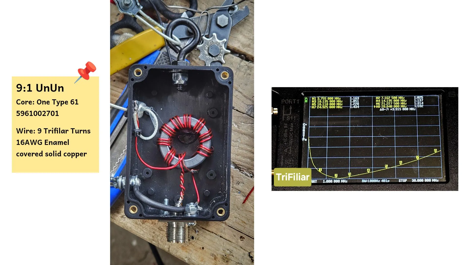
TLT Examples
73 de VE5REV