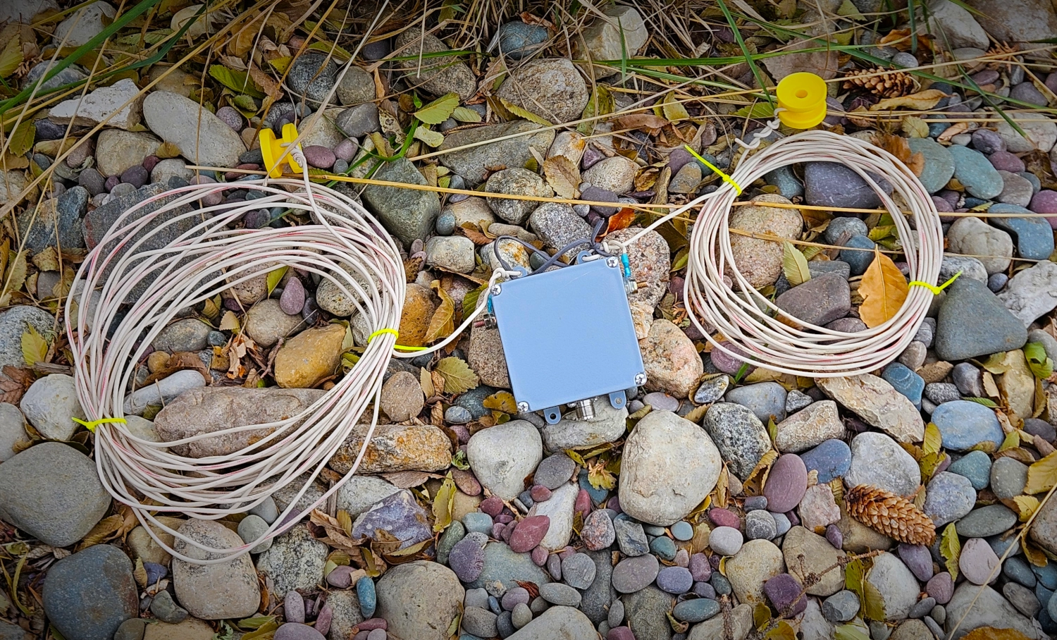
Residential Off-Center Fed Dipole
A truly awesome QTH or portable antenna is the Off-Center Fed Dipole. These and variants have been long used by hams to get on the air with added gain. A true multi-band antenna you get 40M, 20M, 15M and 10M with only slight tuner touch ups. Larger versions can be built that will handle 80M-6M with a beefier tuner. The focus here is the “residential” variety - meaning it is a more compact build, fitting into most residential lots. What makes this “residential” is the shorter overall length. Also, it’s not the usual 1/3 2/3 split of typical OCFD antennas. This one uses 41’ and 27’ sections or a 60/40 split. In discussion with Rick, DJ0IP, he recommends a 59.7/40.3 split. This is a minor tweak to the overall design of this antenna as specked in the PDF file.
Introduction
I found out about this antenna originally on YouTube. Then I came across this awesome presentation from Ted W3TB. I emailed him and he sent me a link to a .PDF file by Dick K5QY that is mentioned in the video. It was originally published in November 2018 in the now offline ‘CQ Magazine’. It has great specs and modelling for the various bands.
The Build
The chief issue to overcome with this antenna is substantial common mode current that can return back down the outside of the coax shield and cause havoc in the shack. Therefore, this equates to the need for really effective of choking. The first step is the process is the “hybrid balun.”
Hybrid Balun Design
The PDF file basically glosses over what is really the heart of this antenna. There is a lot of debate about this but after lots of rabbit holes and first hand testing, I have settled on a 4:1 voltage transformer (Ruthroff) paired with a 1:1 current choke (Guanella) to make up the hybrid balun. What you get is a very effective hybrid balun made up of the best of both worlds - voltage transformation to bring the ~200Ω impedance down to 50 and the 1:1 to isolate the coax and prevent it from radiating.

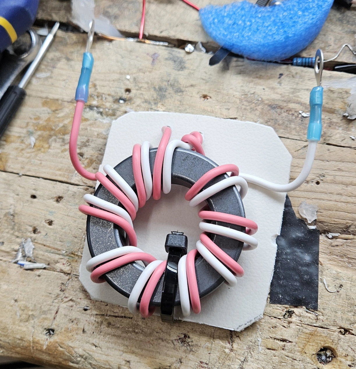
The Ruthroff transformer functions as a Transmission Line Transformer so the turn count isn’t critical to the build. It will be more dependent on your core type than the typical way we think about voltage transformation in an EFHW. I found that 10 bifilar turns is generally quite good. I prefer the turns to be in parallel rather than twisted pair. It seems to do a better job with coupling. For the choke, I highly recommend using 12 turns of coax (RG316). This combination works very well.
Further Info on Hybrid Baluns: There is a lot of false/dubious information on the internet about this topic. Please check out The Hitchhiker’s Guide to OCFD. Rick, DJ0IP has got YouTube videos, PDF downloads and everything there. This is not some “keyboard expert” in a Facebook forum! This is all compiled, first hand field research. It doesn’t get any better than this as a resource on hybrid baluns.
The Cores
I built two versions of this antenna, one for the QTH and one for POTA/Portable. Neither of these builds are used with more than 100 watts.
For the QTH Version I used the larger FT240-61 Size: 2.401” (61mm) OD. Core: 5961003801 for the Ruthroff and FT140-43 Size: 1.4” (35.55mm) OD. Core: 5943002701 for the choke.
For the POTA Version I used FT140-61 Size: 1.400” (35.56mm) OD. Core: 5961002701 for the Ruthroff and Type 31 Size: 1.142” (29.01mm)OD. Core: 2631801202 for the choke.
Type 61 is recommended for the voltage transformer. It has better performance and thermals for 40M-10M. If you’re making a larger version for 80M I would choose Type 43 instead. It does a better job on the low bands.
The choke is effective with either the 43 or the 31. I would default to type 43 but the smaller size of the type 31 used is helpful on smaller builds like in the POTA version.
QTH Version Build Notes
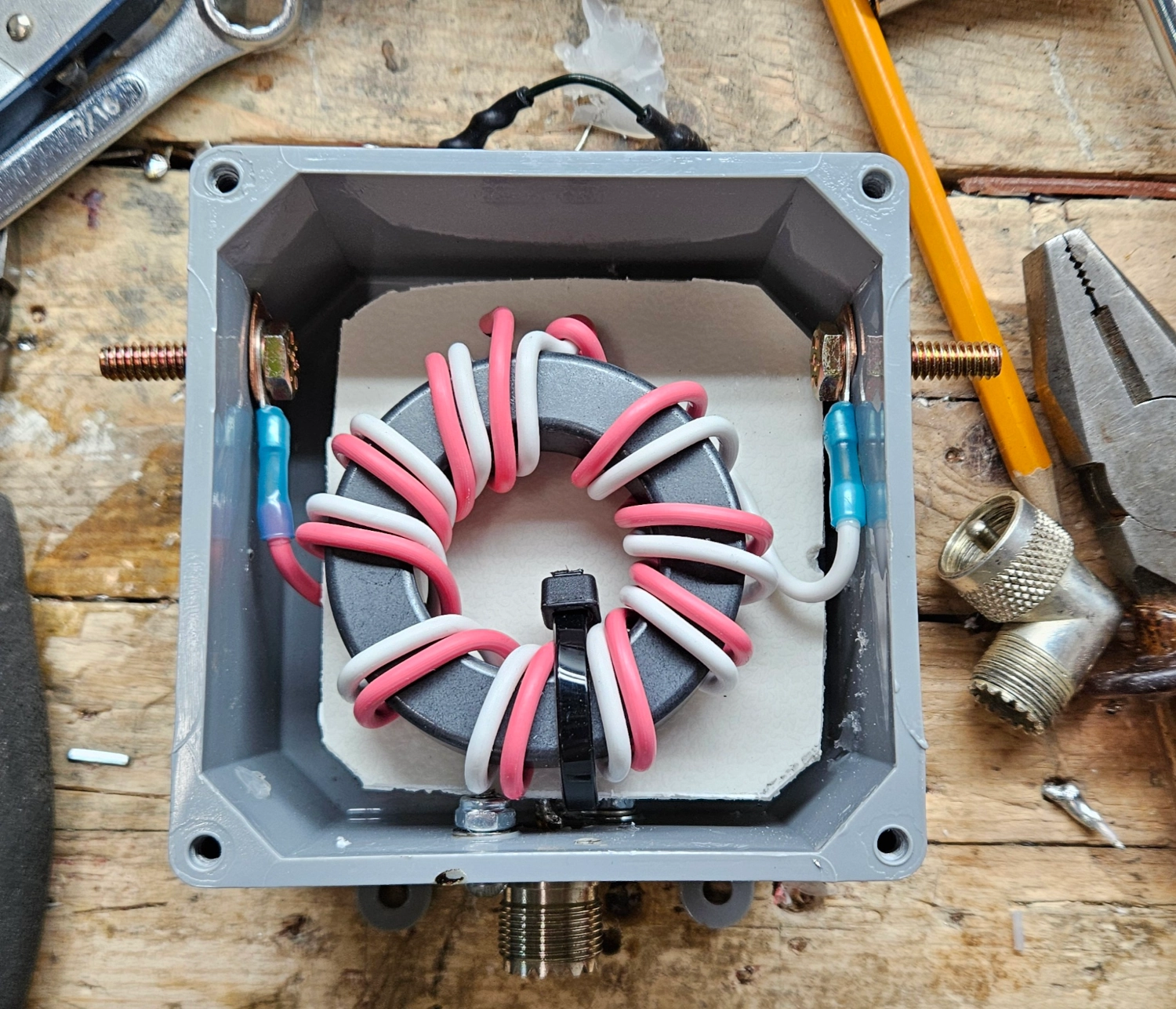
For the enclosure, I used an gasket-sealed, exterior electrical box which is really robust. I drilled 2 1/16 inch holes in the bottom for any water drainage.
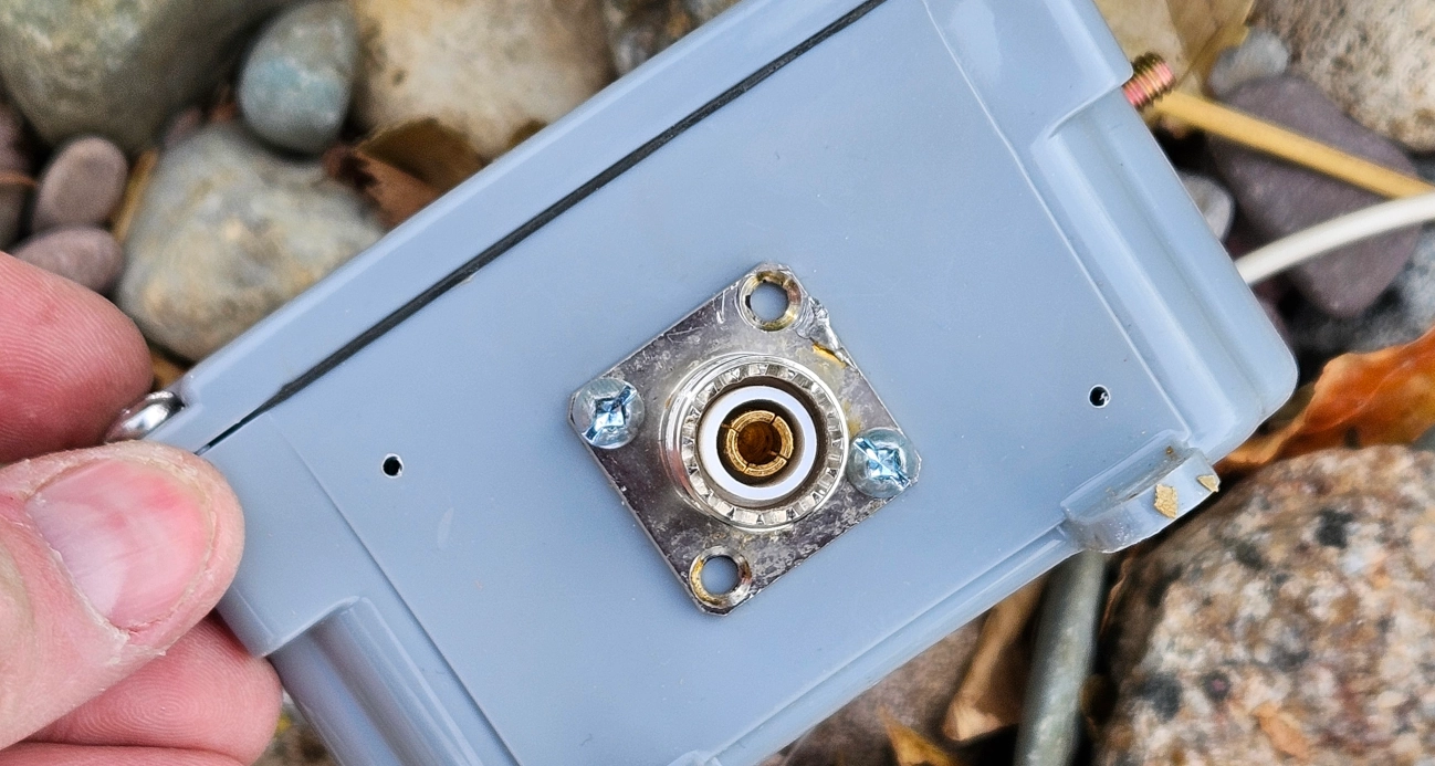
I installed the SO-239 and soldered in the choke.
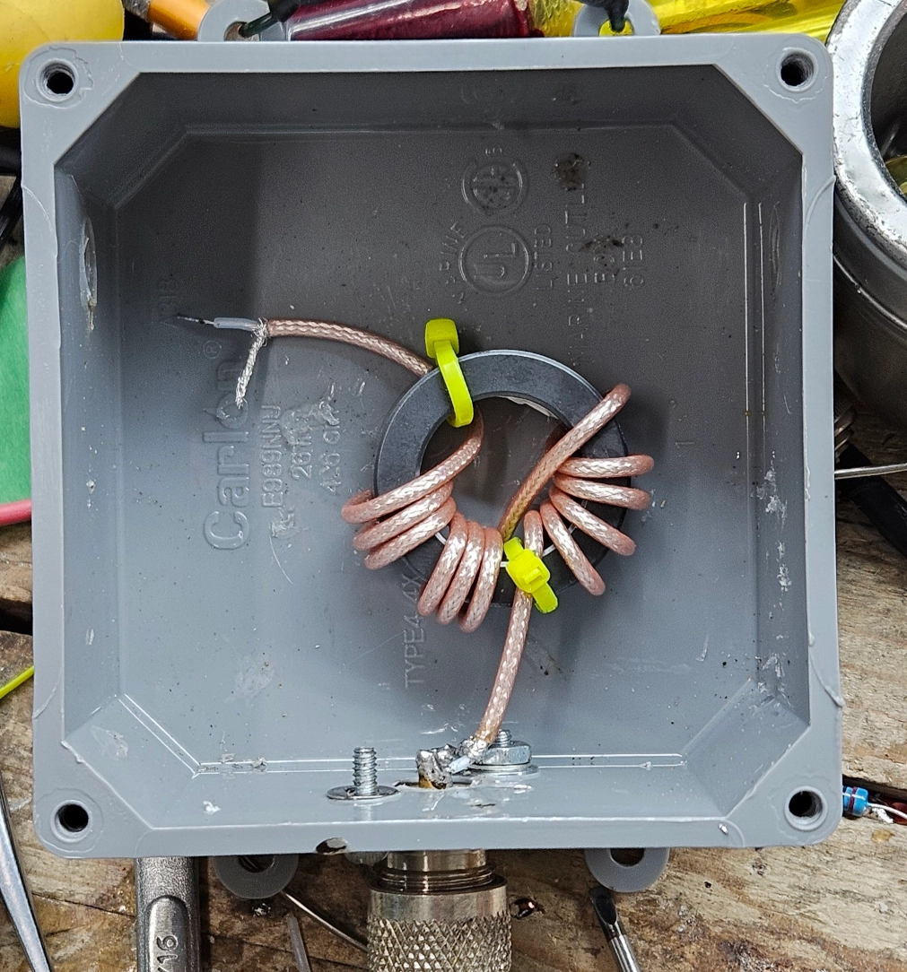
Next I fixed the transformer to a piece of cutting board with a zip tie to have some separation in the box between the choke.
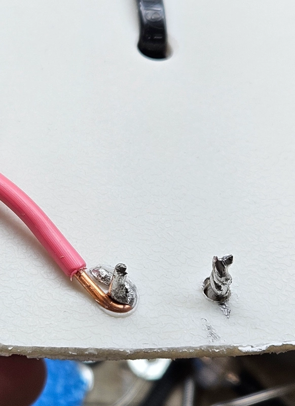
I brought the solder connections through the cutting board to make it easier to solder the choke to the transformer. This also facilitates the coax center/long leg jumper piece connection.
I installed some 1/4 bolts for the antenna leg mounts and installed the hybrid balun inside the box.
Mini Version Build Notes
The QTH version is super heavy and meant to stay up all the time. I tried using it portable and it’s a headache you don’t need. I wanted a smaller, lighter setup for portable work so I built the mini version. It’s just two cores held on a piece of cutting board with zip ties. I used banana plugs for the antenna leg connections. This is a very lightweight and fairly compact setup.
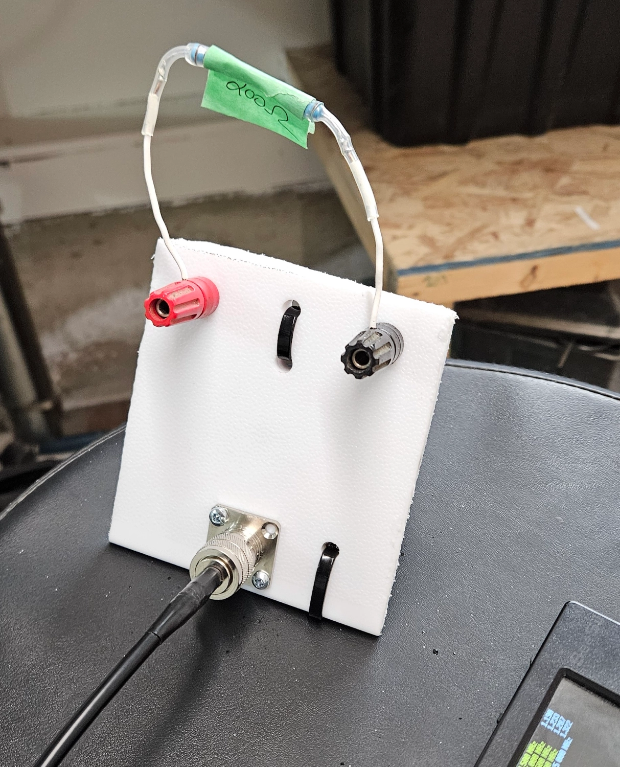
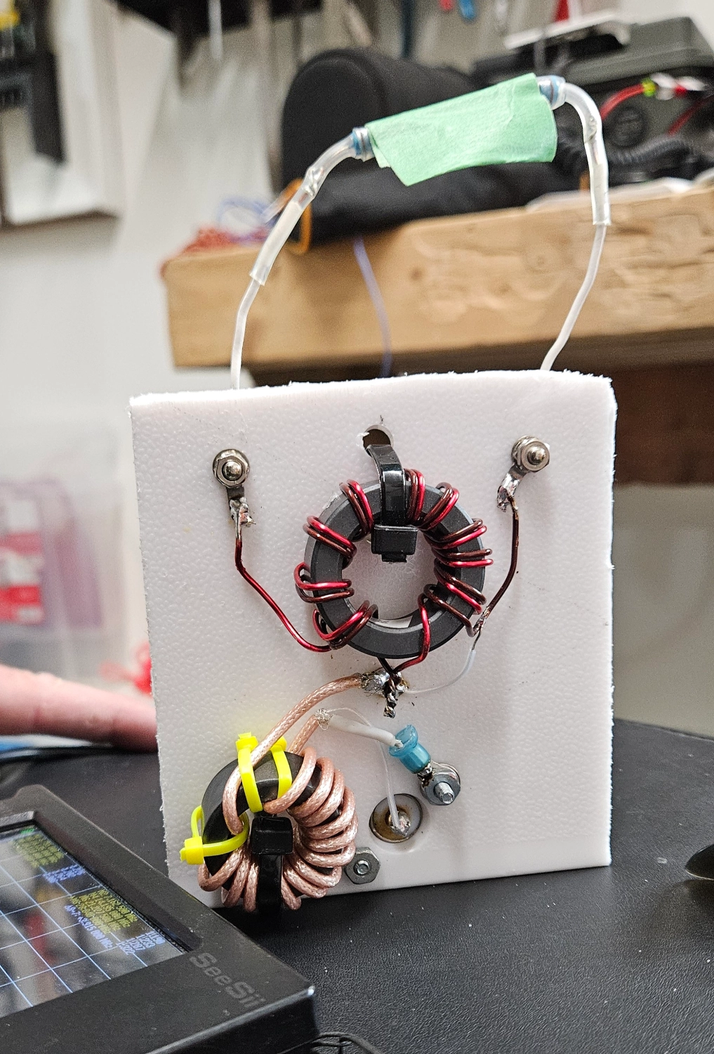
Not shown in the picture are some strain relief holes for the antenna radiators as well as spraying the core side with clear FlexSeal to help protect the connections and keep everything together.
Core Wire
For the QTH Version I used 14AWG house wire because I had it on hand. It’s fun to wrap the larger cores with the bigger wire. However, it’s truly overkill for 100 watt applications and as shown below, doesn’t quite perform as well as the enamel wire I used on the Mini Version. If you have access to teflon wire, I’d probably use that. It has great thermal ratings.
Antenna Element Wire
For the QTH Version I had some 14AWG solid core copper wire on hand so I used it. For the Mini Version, lighter is better. 22AWG silicone wire from BNTECHGO is very lightweight and easily packable.
Testing
NanoVNA
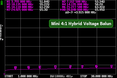
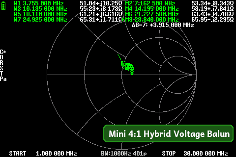
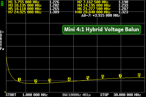
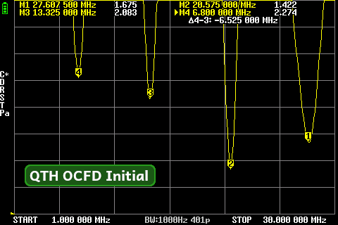
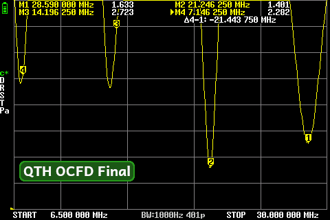
For bench testing, I used a 200Ω resistor load. The results are really great, especially the Mini Version.
QTH Version:
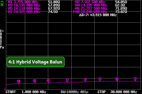
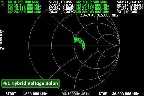
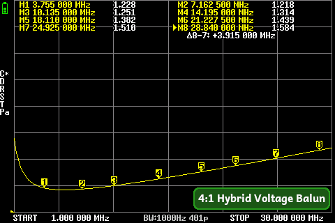
Mini Version:
Antenna Deployment
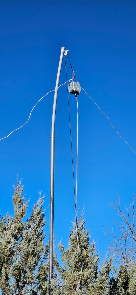
For the QTH Version, I set it up on a mast and had the legs extended to nearby trees. It’s a bit of a process to setup when you have to weave in and around branches! But eventually I was successful. I was sure to use self amalgamating tape covered with electrical tape for the coax connection too. The only configuration that works for my yard is to have the long leg running north and the short leg running south.
I left the antenna radiators a bit long as I always do and true to form, it was a bit long.
When trimming the radiators, I maintained the 60/40 ratio, trimming from both the long and short legs. The final results are not too shabby. My goal was “close enough” for a tuner. And it turned out pretty good, 20M being a bit higher than I’d like but 15M & 10M are really good. 40M too is easily tunable. I could have sniggled a bit more and got 20M a bit closer, but as is, an internal rig tuner can easily clean these bands up. Using my LDG tuner, I was able to tune 40M-6M no problems - even 30M which is generally a bit uncooperative.
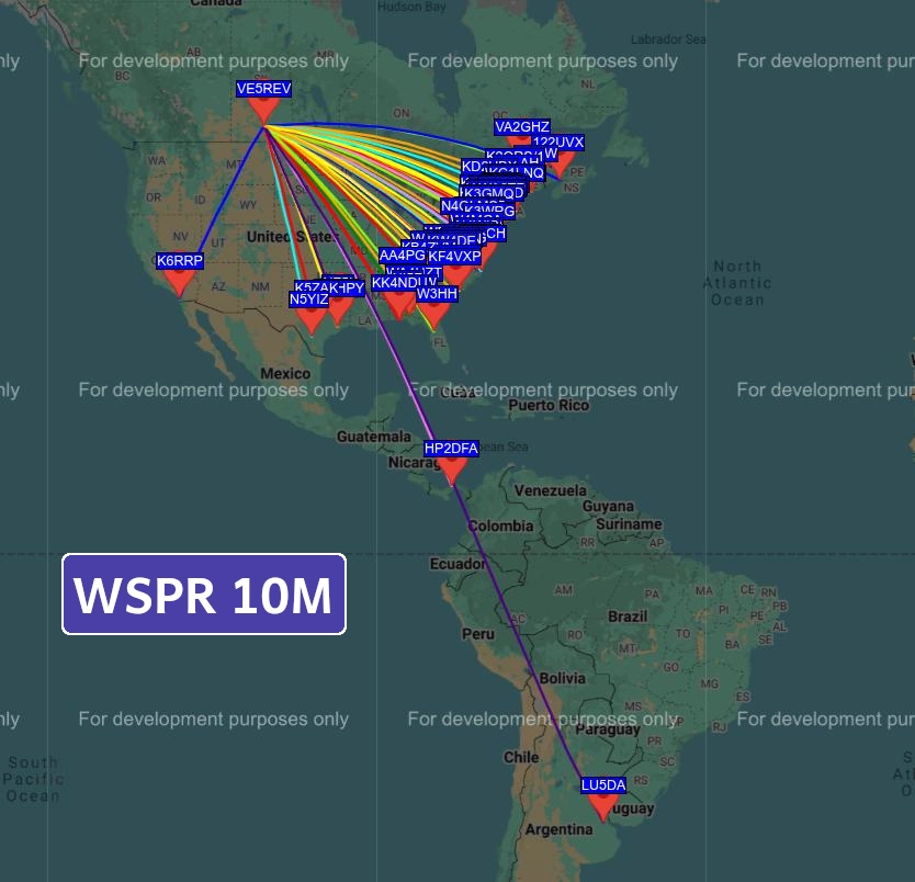
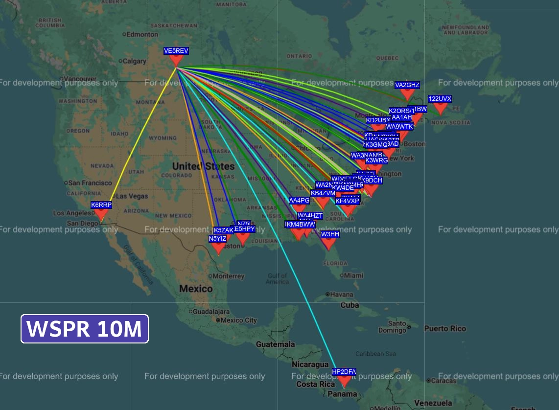
WSPR
I ran my standard 20 minute, 1 Watt tests on all 4 bands. The IC-705 had no problems from CMC, but I was also using my QTH 1:1 choke at the rig.
10M
15M
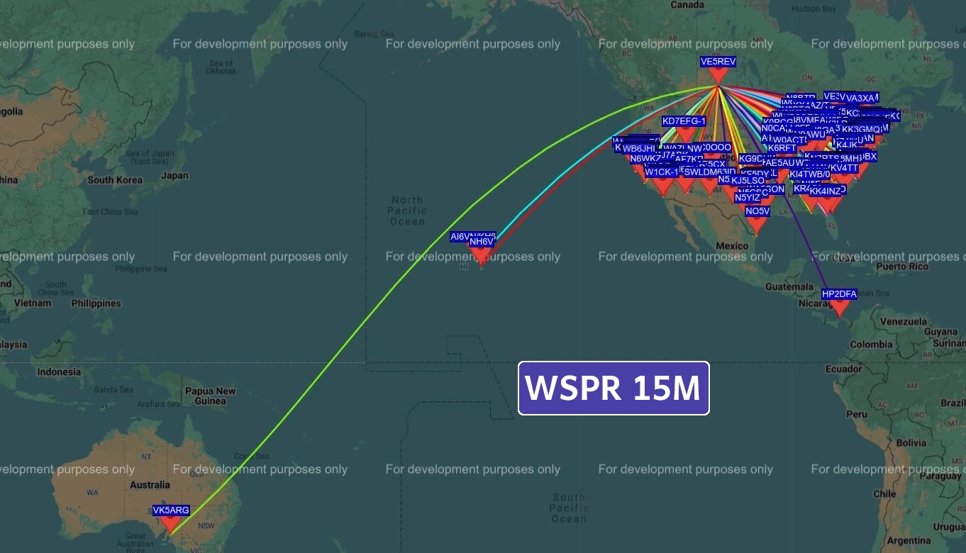
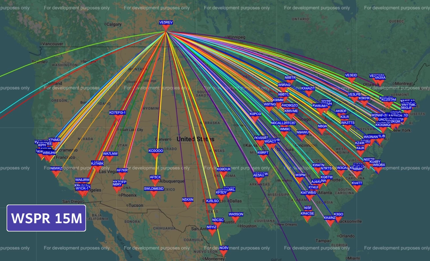
I got 180 contacts on the 15M band.
SNR: Max: +06 Min: -31 Avg: -13
KM Distance: Max: 14,623 Min: 1071 Avg: 2396
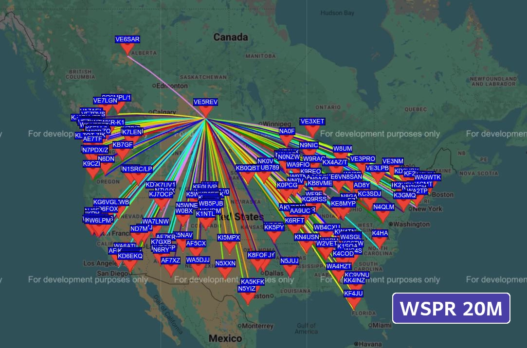
20M
I ran another 1 Watt test on 20M just to check the pattern. It’s quite well distributed.
40M
I ran an additional test on 40M:
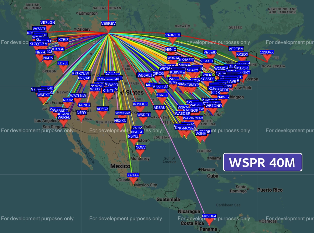
300 Contacts with a bit of DX. The straight north line was an anomaly.
SNR: Max: +07 Min: -31 Avg: -13
KM Distance: Max: 2793 Min: 872 Avg: 1972
Summary
OCFD dipoles are awesome antennas. They are stellar multi-band performers. Deploying them for portable operations can be a bit tricky as you need 3 tether points ideally. It’s definitely not a quick setup process. However, as a QTH antenna or a camping setup where you are going to be in a place for a few days, it’s a more than solid option. Resonance without a tuner may be a bit tricky depending on deployment height, but with a tuner you’re golden. In my mind, the EFHW is still King for portable work due to sheer convenience. Both of these antennas are comparable gain-wise, 2-3dBi on fundamentals and then 5-6dBi on the higher bands in peak directions. Where the OCFD shines is having more directivity which may be an advantage for working a specific direction.
73 de VE5REV