NVIS

I first became interested in Ham Radio from the preparedness perspective. Far from a hardcore prepper with a bunker, I simply wanted to have a means of communication if the internet ever went down. Our entire society has all of our collective eggs in that same basket. I remember being in a store when the interac/digital payment service had an outage. It was utter chaos. Nobody could buy or sell anything. Even cash didn’t work because the transactions needed to be accounted for on the store’s digital platform. It’s all fine and dandy until it fails. This is what got me on the de-centralized communications path.
Local Communications
When first getting into amateur radio, you come across the HT or handy talkie. I’m sure everyone’s first radio is probably one of these. A Baofang or whatever. I bought the Yaesu FT-65R which I still have. It’s a great radio. You play around with them and learn lots about simplex and repeaters. But what if you don’t have repeater infrastructure? Then the line-of-sight VHF and UHF stuff likewise can become less useful - or at the very least, doesn’t solve the problem of regional or local communications.
NVIS
Enter the NVIS. Near Vertical Incidence Skywave - a radio propagation technique used precisely for reliable short to mid range communications, generally from 0-650km/0-400mi. The concept is that the radio signal goes up, bounces off the ionosphere and comes back down again. There’s loads of YouTube videos about this topic for further study:
NVIS: Bands
Typically, NVIS propagation works best from 1.8-8MHz or the 160M, 80M, 60M & 40M bands. Practically speaking, this is the 80M band at night and 40M band during the day/evening.
NVIS: Antennas
There’s not really a specific NVIS antenna per se. You use your regular horizontal antennas for 80M or 40M but you deploy them lower than the optimal/DX minded half wave length above the ground. For NVIS it is generally recommended to go .1-.25 of a wavelength. So for 40M that is between 13’-32’(4-10m) and for 80M 26’-66’(8m-20m). For field work, these heights are still kinda high to be convenient. What happens if you deploy them lower than these scientifically determined heights?
NVIS: How Low Can You Go?
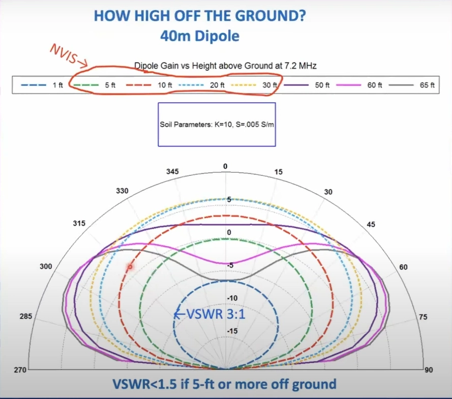 I took this screenshot from the SnoVARC NVIS Antenna Presentation. It depicts antenna modelling at various deployment heights above ground. You want the RF bubble to be ball basically, rather than the long distance friendly squished pattern which throws the signals out farther along the horizon. What I’ve noticed in practice (and is referenced in this image) is that when you deploy a 40M antenna low to the ground, the SWR goes way up. The image shows 3:1 SWR at 1’ deployment height. I wondered if there was a way to deploy the antenna lower but still have SWR under 2:1 across the 40M band.
NVIS: EFHW
Dipoles are great antennas but for field deployments, they’re a bit of a hassle. Realistically you need 3 tie-off points. 1 to hold the center feedpoint/weight of the coax and 2 for the ends of the elements. This is where the EFHW has the distinct advantage as you only need 2 tie-off points to deploy it. 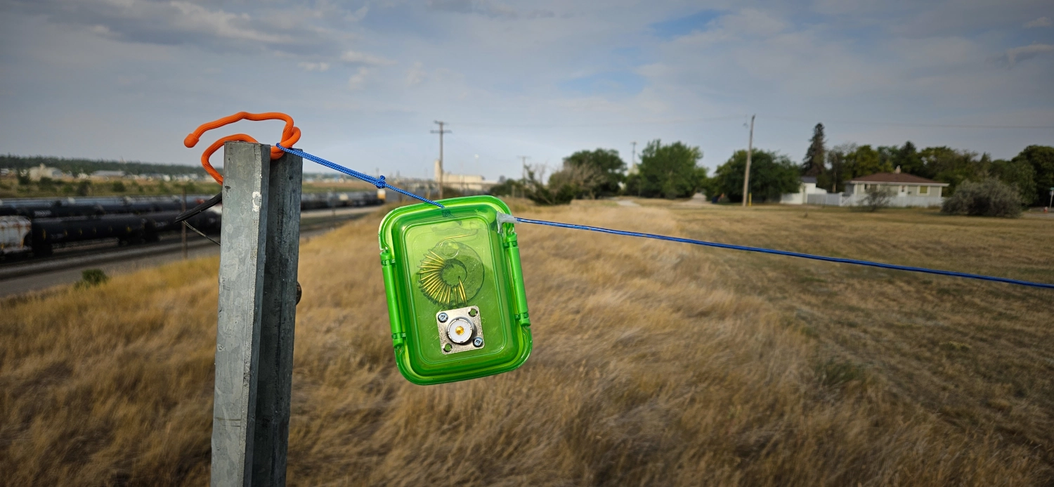
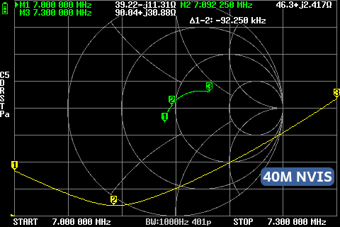
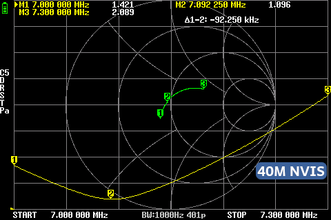
I built a special transformer for the NVIS deployment on 40M. In my field tests I discovered that as I went up from 49:1 to 56:1 to 64:1, the SWR response on 40M got better and better with a low to the ground deployment. So I tried something crazy and built an 81:1 ratio (2:18). Low and behold, I was able to get the entire 40M under 1:2.0 SWR. These NANO VNA readings were from about a 7’ deployment height. I left the resonant point on the lower end for CW/Digital but it could be trimmed a bit and bring the resonant point towards the middle of the band and be closer to 1:1.6 at a maximum across the band.
Antenna Specs
- Wire: ~66’ of 18 gauge speaker wire
- Core: 1.540” Dia (39.12mm) OD. 2643251002
- Capacitor: CC45SL3FD101JYNNA 100 pF ±5% 3000V (3kV) Ceramic Capacitor SL Radial, Disc
- Transformer Wire: 18g enamel, 2:18 ratio, auto-transformer build
- Counterpoise: ~6’ (~.05λ for 40M) un-choked coax
- Choke: 1:1 choke to isolate the rest of the coax feedline
- Deployment Height: ~7’ above the ground
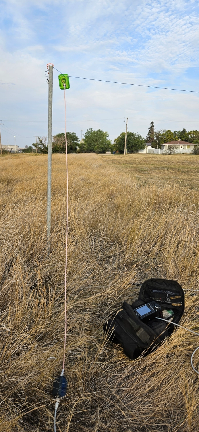
WSPR Tests
I did two separate WSPR tests with this antenna from the same location. The first one at 12 Noon local time to test daytime propagation and the second test at evening/greyline. Both tests were 1 watt for 20 minutes. The Antenna was deployed at about 7’ above the ground and ran North-South so that the broadside of the antenna faced East-West.
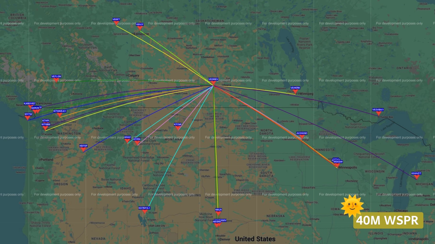
Daytime Test
- Total Contacts: 79
- SNR: -28 to +09. Avg: -16
- Distance: Min - 579km. Max - 1663km. Avg - 1080km.
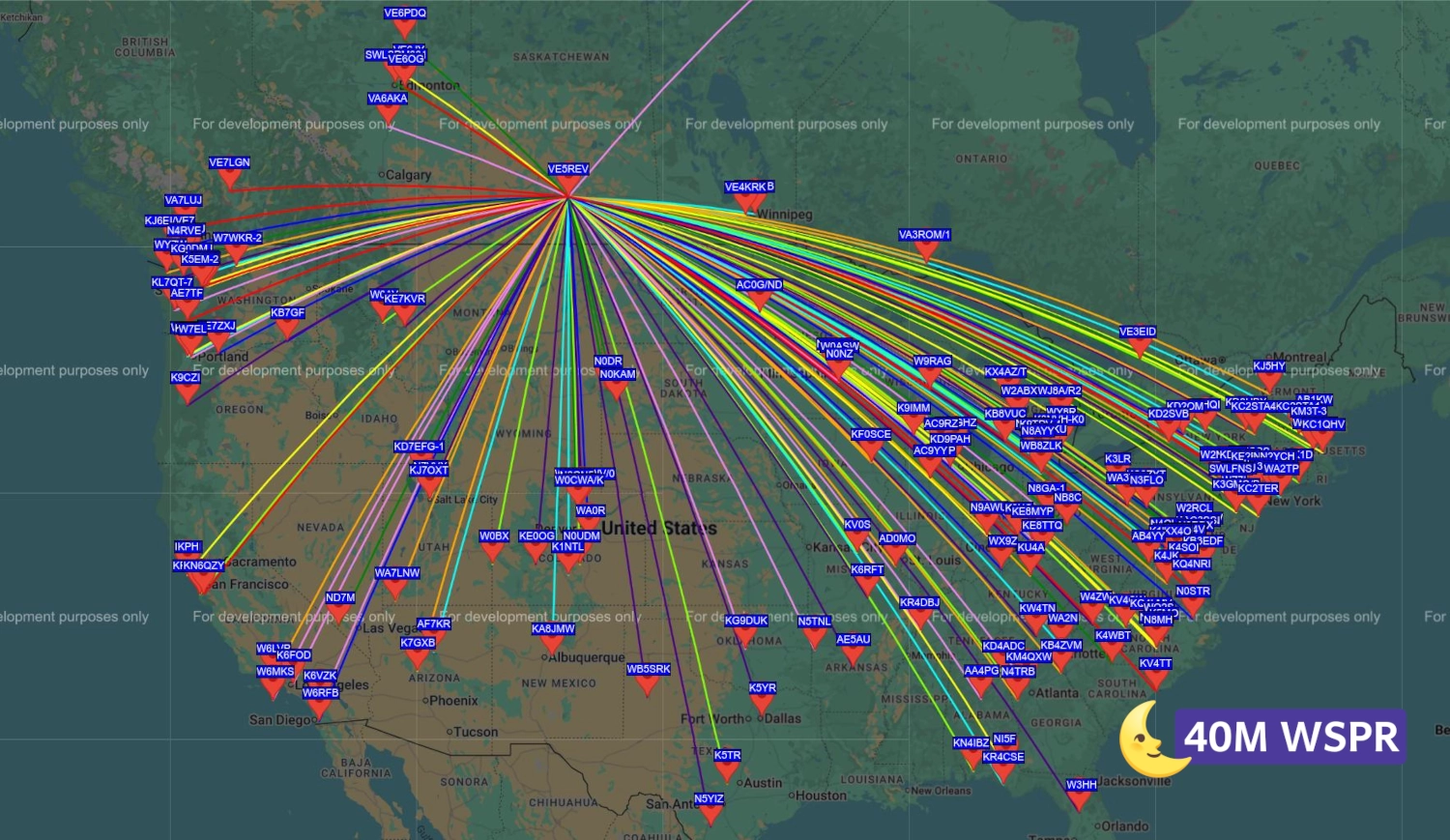
Nighttime Test
- Total Contacts: 474
- SNR: -30 to +13. Avg: -15
- Distance: Min - 579km. Max - 2853km. Avg - 1877km.
Results
The daytime test definitely showed the NVIS propagation with several Canadian stations in adjacent provinces within that 500-700km range. There were also quite a few more US contacts than I expected for the daytime test. The evening contacts are truly mind blowing considering the antenna is running North-South. We can glean from these results that the NVIS RF pattern is much the same as a vertical - a nice, round bubble of omni-directional RF. The signal truly goes up and comes down during the day. And in the evening, as the ionosphere layers change, we see the propagation reaching farther and farther. Very interesting test results indeed!
73 de VE5REV