EFHW
UPDATED: 20250425
The End Fed Half Wave antenna is the King of portable antennas. Truly it is a near perfect match between portability and performance. They are extremely quick to setup and extremely good performers as a resonant antenna that does not require a tuner. Long used for SOTA and POTA operations, the convenience and flexibility of this antenna system is truly hard to beat.
Introduction
As with everything on this site, the following notes are from first hand research and testing.
With the advent of Parks On The Air (POTA) and Summits On The Air (SOTA), the interest and popularity of portable radio operations has soared in recent years. And with that popularity has come the quest to find portable gear and antennas that are convenient, easy to pack and still work great. One such antenna that has risen to the top of the portable choices is the End Fed Half Wave (EFHW). These antennas have a resonant radiating element that is 1/2 electrical wave length long. Feeding this antenna at the end of the wire (rather than in the middle as with a typical dipole) presents an impedance mismatch that must be dealt with. A center fed dipole has around 72Ω impedance. An End Fed can have an impedance of 2000-4000Ω. Thus it requires a high impedance matching device or transformer.
EFHWs are great portable choices because they are easy to deply. Only one end needs to elevated using a mast or a tree. The feed point can be near the ground or it can be up high. You can use many configurations for the wire too from vertical to sloping to inverted Ls and Vs. Also, you do not need any additional ground/counterpoise wire as the EFHW will use the coax shield for this (however, this results in less optimal performance). And, these antennas are efficient because they are resonant and do not require a tuner. They are multi-banded as well in that they will be resonant on band harmonics. You can easily ground them too to dissipate static build up and maintain a low DC potential.
The transformer is the key to making this antenna successful. Essentially an L-Match, they typically use a Type 43 ferrite toroidal core wrapped with enamel coated wire. Recent experimental work has been done with other core types too, including 52 and 61. Also, new core geometry has been found to provide incredible efficiencies of over 90%. The other component needed for this antenna matching circuit is a 100-120pF capacitor.
The Build
Toroid Choices
This can vary depending on the deployment (QRP or QRO). For years the standard choices have been Type 43 in the larger 2.4” or smaller 1.4” sizes. However, my recommendations are the following:
- QRO - Type 43 Size: 1.540” (39.12mm) OD Core: 2643251002 [$12.22 in 2025] Efficiency Research

- QRP - Type 43 Size: .827” (21mm) OD. Core: 5943000601 [$2.09 in 2025] I used 2 Cores Stacked. Efficiency Research. Also worthy of consideration maybe this core, but I have not tested it first hand: Size: .500” (12.70mm) OD. Core: 5943001101 [$0.94 in 2025]
- Either Use - Type 61 Size: 1.020” (25.91mm) OD. Core: 2661102002 [$8.33 in 2025] Highly efficient & compact core with high temperature rating which is great for digital modes like FT8.

Capacitor Choices
This is really a one stop shop as far as I’m concerned.
For 49:1 & 56:1 ratios, use a 100 pF capacitor: CC45SL3FD101JYNNA
For 64:1 & 81:1 ratios, use a 120pF capacitor: CC45SL3FD121JYNNA
120pF is also recommended if using the above Type 61 core.
Winding Pattern
The pattern consists of primary and secondary turns to facilitate the voltage transformation. Here’s how it works:
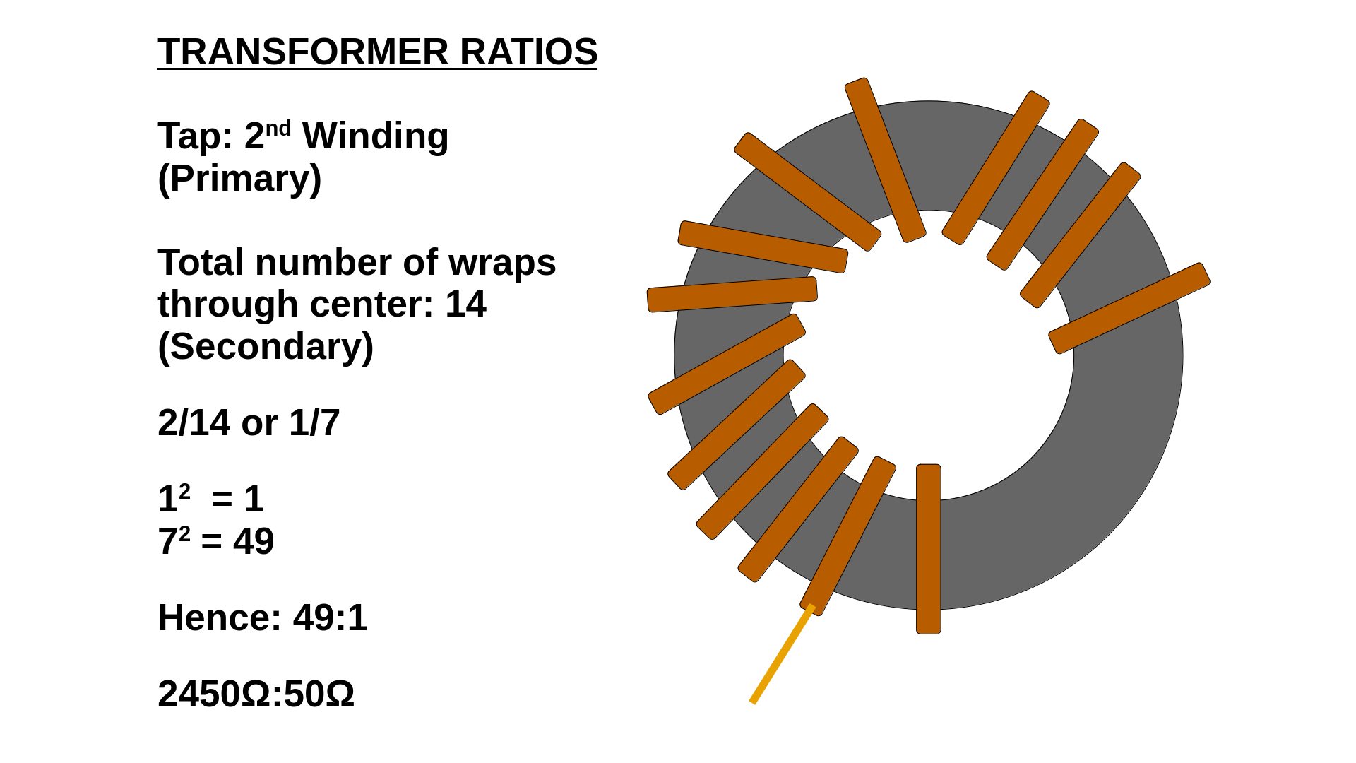
From experimenting, the tried and tested 49:1 ratio is easiest for multi-band performance. The harmonics seem to line up the best. a 40m EFHW will give you resonant operation on 40m, 20m, 15m and 10m.

I also experimented with 56:1, 64:1 and 81:1 ratios. What I determined is that for mono-band use the 56:1 really performs well. As does the 64:1. I deployed the 81:1 for a 40M NVIS EFHW and it worked swimmingly well. The extra inductance really seems to help bring the SWR down on low mounted EFHW antennas like an EMCOMMs NVIS style antenna.

You can use alternative windings to 49:1 and still obtain multi-band performance, but it will require the use of an inductor coil about 6’ from the feed point. This can be seen in many commercial EFHW products. The coil is just the antenna wire wound on a plastic/PVC/whatever pipe. This coil helps make the top bands cooperate better on harmonics. I fought with this for quite a while using the 56:1 but eventually gave up and went with the 49:1 for multi-band. I could see using this setup as a QTH antenna or for a longer setup like when camping. But for quick POTA operations, I prefer a monoband vertical EFHW up the DX Commander mast using a 56:1 or 64:1. Just swap wires to change bands.
Counterpoise
You often hear the EFHW doesn’t need a counterpoise. This is untrue. There is always some kind of counterpoise, whether it be the feedline coax or a dedicated counterpoise wire.
The rule of thumb is that this should be 5% of a full electrical wavelength for your lowest operating band.
The following chart shows these length measurements for the center of the Canadian Band plan frequencies. You can adjust for CW/Digital as needed.

A.B.C. Always Be Choking
After some WSPR tests to check radiation patterning, I have concluded that using the full feedline length of un-choked coax as counterpoise for ‘convenient and fast deployments’ really isn’t optimal. It will certainly work and I have made lots of POTA contacts this way. However, what can happen is the intended radiation pattern can get skewed in unintended ways. And it is possible that your coax might end up radiating more than the antenna! In this case, the RF is largely going into the earth rather than up into the ether where you want it.


Recommended Configurations
After much testing, the following configurations are recommended for optimal performance:


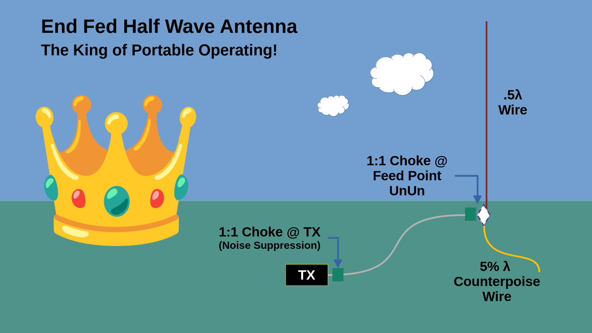
The choke at the rig eliminates line noise that the coax might pickup (Radio manufacturers really should just build this into all radios at the factory!). And the choke at the UnUn isolates the coax from radiating, keeping the antenna pattern cleaner.

A Note on Hybrid Transformers
UPDATE: My original post was advocating using a hybrid or combo UnUn that had a 1:1 choke along side the transformer. After more experimenting with this, I have decided that I prefer to use a separate 1:1 choke and an un-choked length of coax as the counter poise (Optimal Setup B above). In operating, I have found that this is easier than managing another piece of wire. I just leave the counterpoise coax jumper attached to the 1:1. I find that this setup is a simpler and cleaner solution.

Deployment Configurations
One of the best things about EFHW Antennas is that they only really require one mounting point. Whether a tree or a mast, it’s much nicer to quickly deploy this antenna compared to a dipole that will require 2 or 3 mount points. It’s incredibly versatile. Deploying the antenna the same way every time will work best for repeatable results.
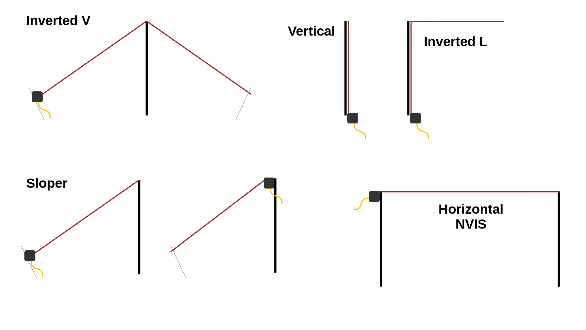
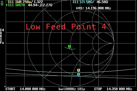
In testing, I discovered that there is a difference in the sloper configuration if you deploy the transformer in a high vs low position. If you tune your EFHW wire with the transformer in low position and then elevate it to a high position, it will be thrown off. Adding height makes the electrical length longer which will lower the resonant frequency. This could be an advantage. I would tune and trim the wire for low transformer height in the middle of the band. Then, if you wanted to use the same antenna to work digital or CW, with lowest possible SWR, you could deploy it with a high transformer height, effectively dropping the resonant frequency into the bottom of the band.

73 de VE5REV
