Double Bazooka Antenna

I stumbled across what is called the Double Bazooka Antenna. It’s a dipole, also known as the coaxial dipole, and it originated way back in the 1940s when MIT Engineers developed it for the US Government radar applications during WWII. The concept is creating a really broadband radiator that is quieter than a traditional dipole. By the 1950s Hams were adapting it for amateur radio use. A QST article in 1968 helped bring this antenna design to a wider ham radio audience.
Build Features
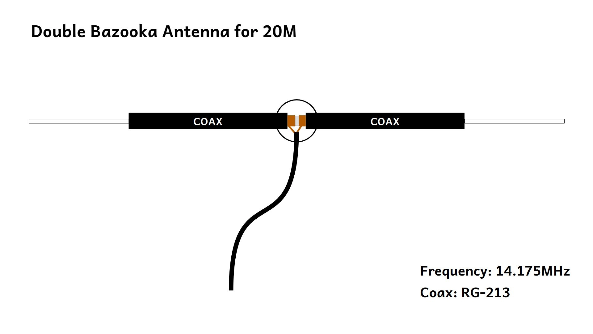
The Double Bazooka functions as a half-wavelength dipole but is up to 14% wider in bandwidth than a standard dipole. It also has better impedance matching across an entire amateur band. It consists of a half-wavelength of coax with the outer shield split at the center feedpoint, where the feedline (50-ohm coax) connects to the open shield ends; the center conductors of each half are shorted at the ends to form quarter-wave stubs. These stubs do not radiate but act as impedance transformers: at resonance, they provide high resistive impedance at the feedpoint, while off-resonance, their capacitive reactance cancels the antenna’s inductive reactance, maintaining low SWR over a wide frequency range. The enclosed coax design also reduces static buildup and noise (by up to 6 dB) compared to wire dipoles, as there’s no exposed metal for charge accumulation. Apparently no balun is needed due to the inherent balance of the design.
Build Notes
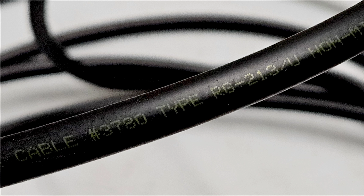
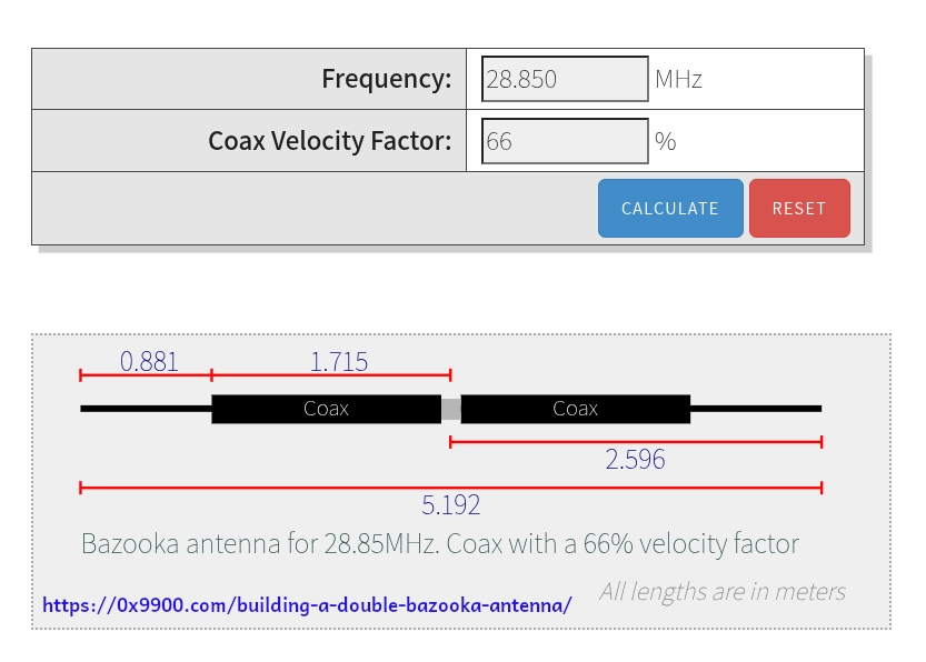
This YouTube Video from 100 Watts and a Wire does a great job illustrating how to build this antenna. There’s lots of antenna calculators online, but I used this one. You pop in your desired frequency and it spits out the correct lengths for the coax stubs and the tail pieces. You have to know the velocity factor of your coax which you can tell from the jacket. Or if it’s unknown you can do some measurements with a NanoVNA.
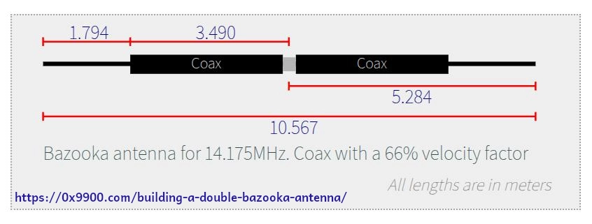
I measured my coax for 14.175MHz, aiming for the middle of the 20M band. According to the diagram, that was 6.98M. I cut it 7M. I then measured back and found the middle, marking it with a piece of wide masking tape. I then carefully cut and peeled off the jacket where the tape was to reveal the coax shield.
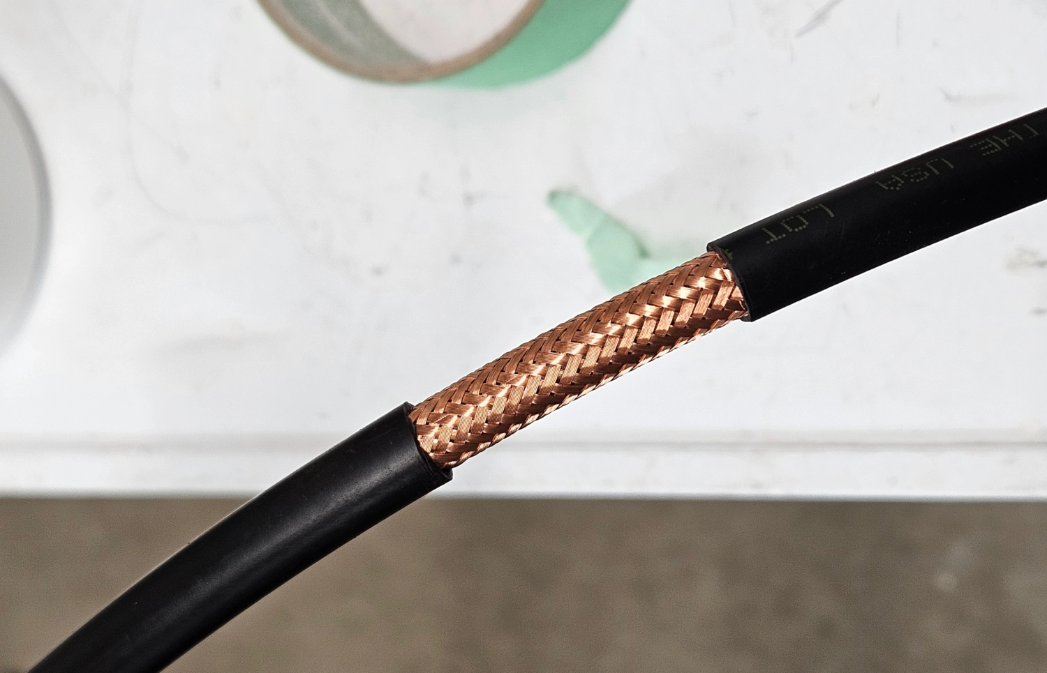
I drilled out a 3.25” PVC cap to serve as the housing. I wanted to use an SO-239 connector, rather than direct soldering in the feedline coax. This worked well but it would be even better with a direct soldered connection, saving the loss of the SO-239. I carefully cut the coax shield in the middle and twisted up the braid on each side. Be very careful not to cut/knick the dielectric beneath the shield. I installed a couple zip ties on the inside of the cap to hold it in place.
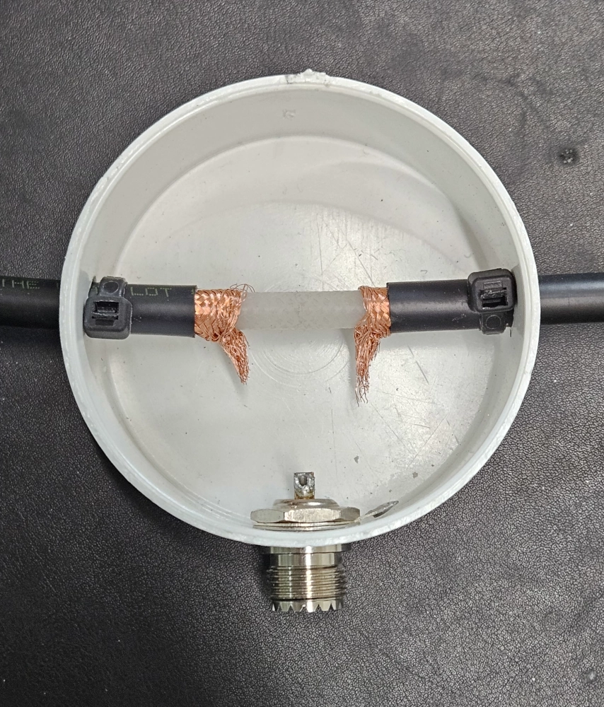
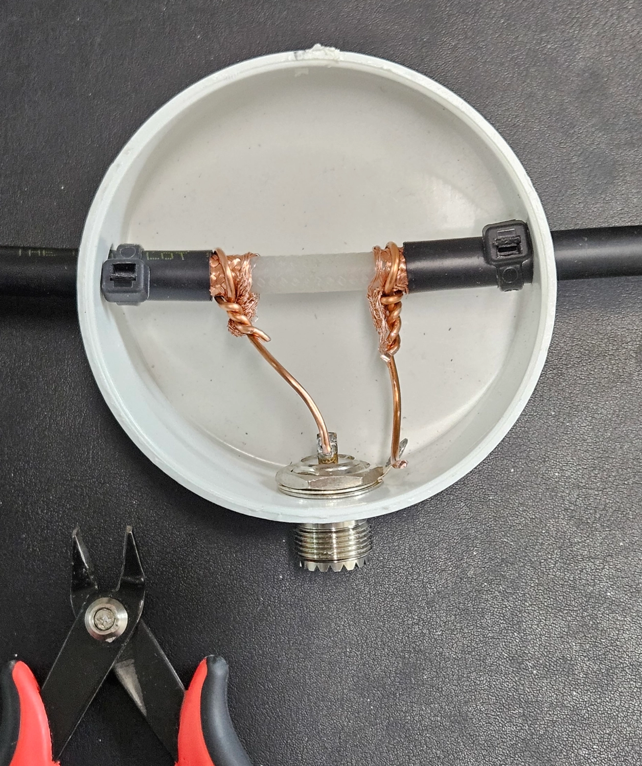
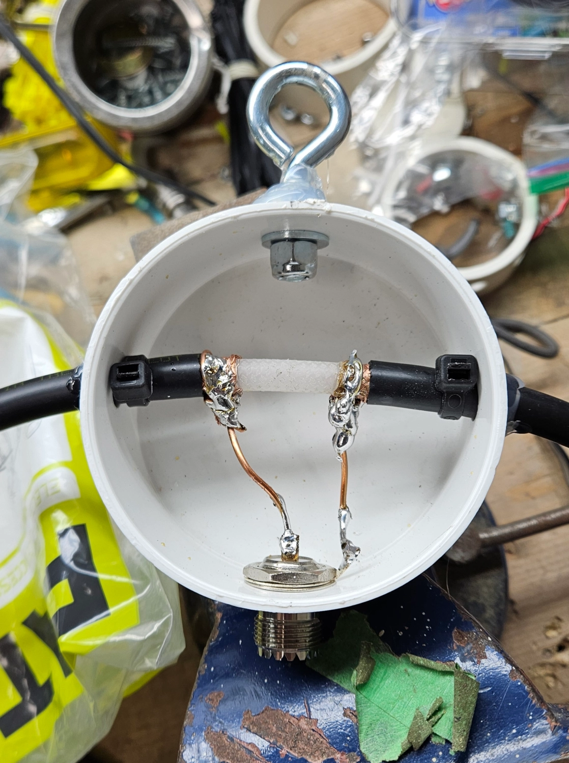
Because of the SO-239, I decided I would solder in some 14AWG copper wire for a nicer connection. This worked out pretty well. I also installed a halyard eye bolt to hoist the center up.
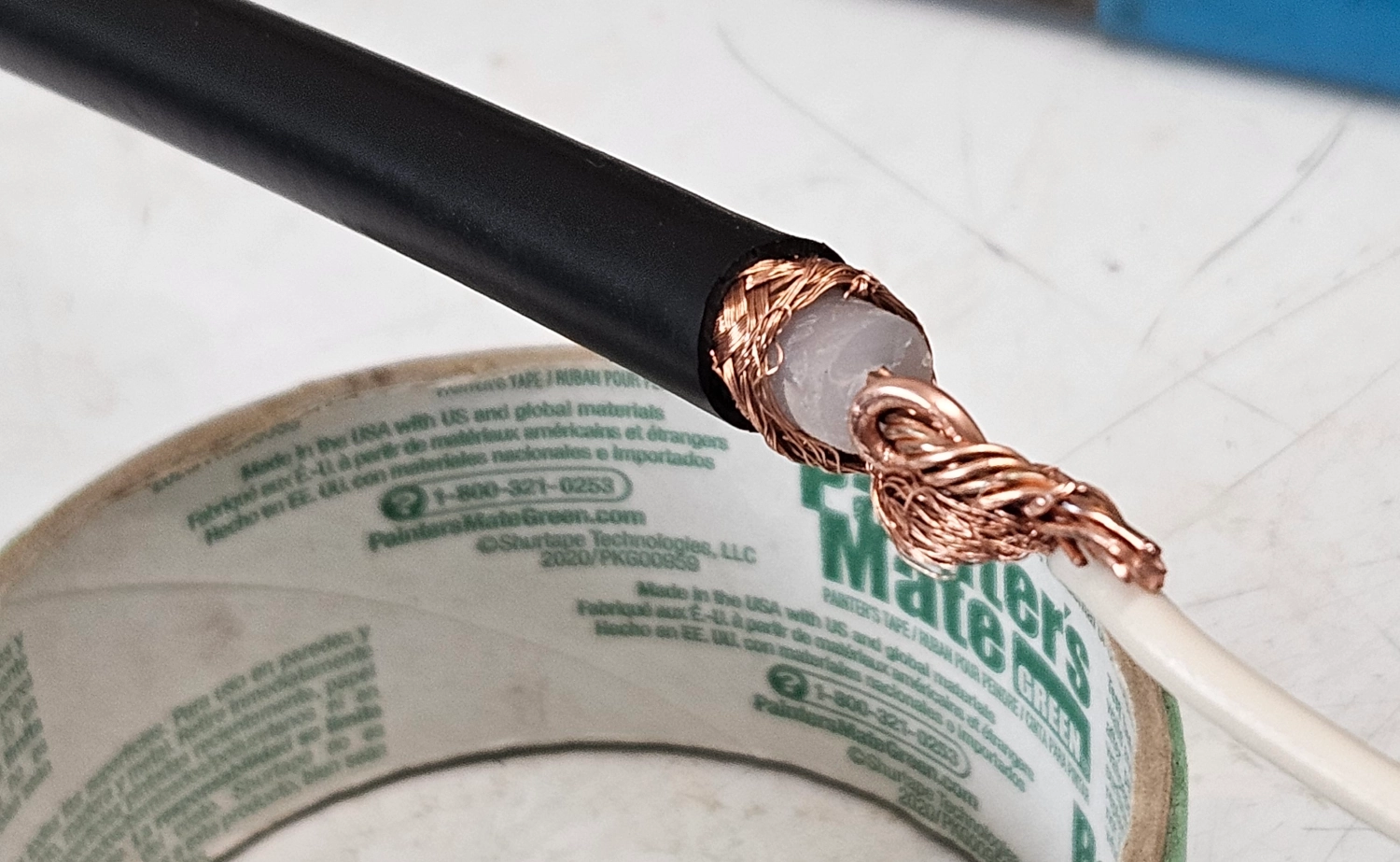
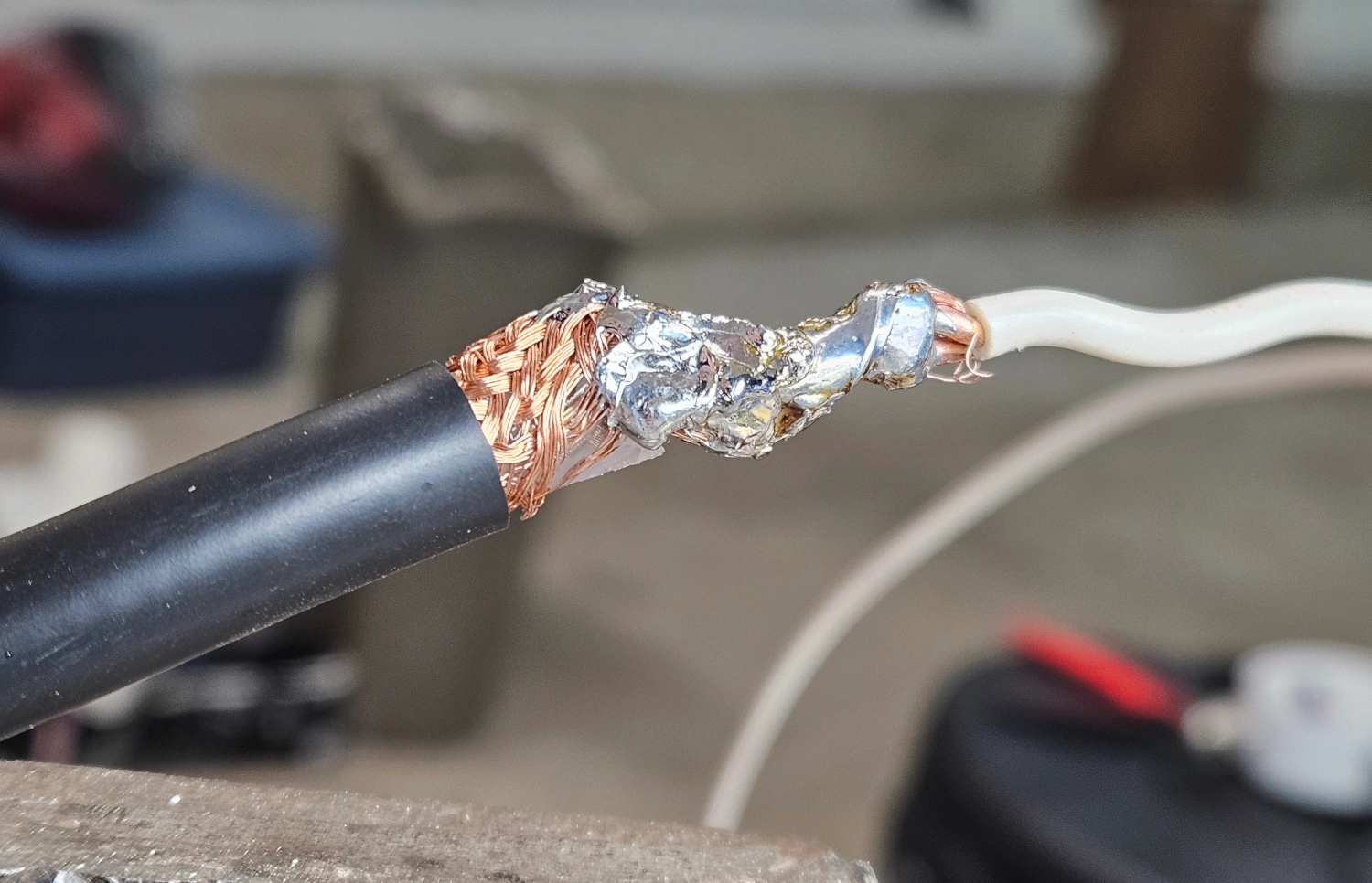
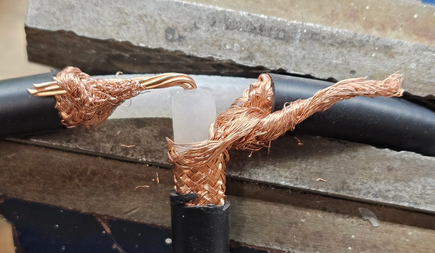
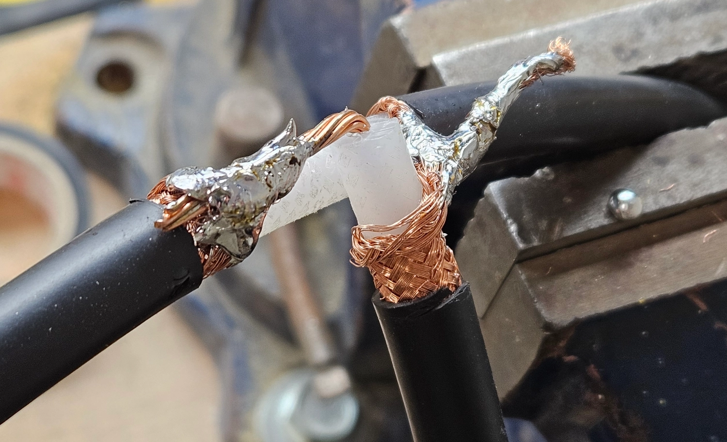
After the center was completed I turned my attention to the legs. This is the finicky part of this build. You need to attach some wire to the coax stubs. I used 14AWG solid core wire for this, cutting it to 2M thinking it would be long and need a trim. It didn’t need a trim! I’m glad I added that extra because it worked out very well. You need to peel back an inch or so of the coax jacket, then roll back the shield, then carefully remove the dielectric, exposing the coax center. This is where you need to attach and solder the wire tail and also solder in the coax shield to short it out. This is kind of a beastly thing with RG-213. I didn’t do it the best way. I twisted the coax shield into one wire and that was not as good as simply rolling it back over the coax center and wire tail connection. It would have made for a cleaner finished connection.
It took forever and a metric tonne of solder to get everything connected. It was all rather beastly. I then installed some marine grade glue lined heat shrink to reinforce the connections and helo keep them together. I was going to install an additional plastic brace piece with zip ties just for added strength but it seems to be holding up without them.
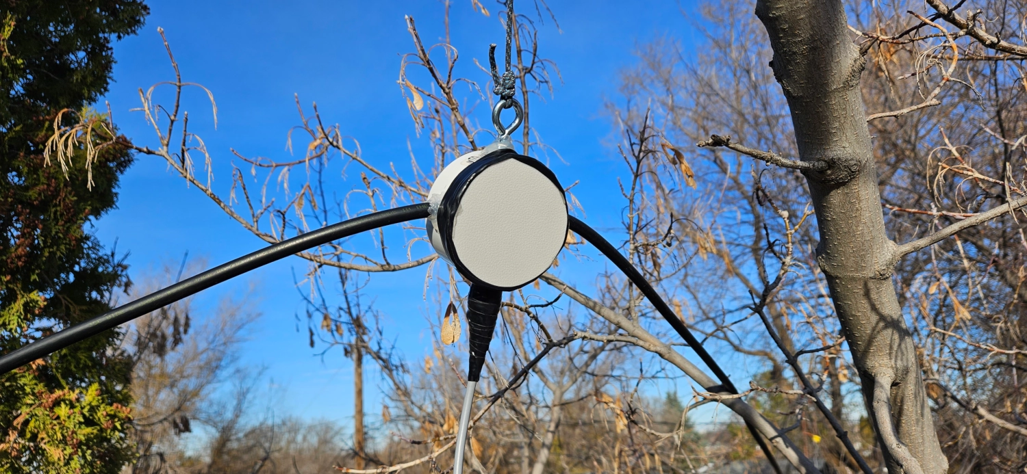
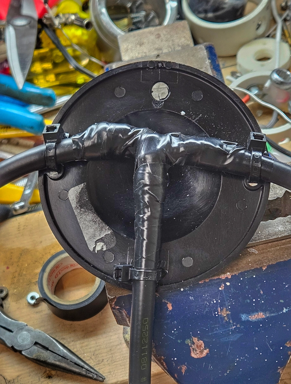
I debated just using liquid electrical tape to seal everything up inside the PVC cap. But in the end, I cut a cutting board plastic cover and fixed it in place with hot glue. I then wrapped some electrical tape around it for added protection. I put hot glue where the legs enter the cap and on the halyard connection too. I got my trees and paracord all set and hoisted everything up into place. I used some self amalgamating tape to seal up the coax connection.
Field Testing
I’ve got the antenna deployed as a flat topper around 20-25’ up or so but it’s got a slight Inverted V aspect to it. The legs are pretty darn heavy. I’ve got a 50’ run of coax back to the shack and I couldn’t wait to put it on the analyzer.
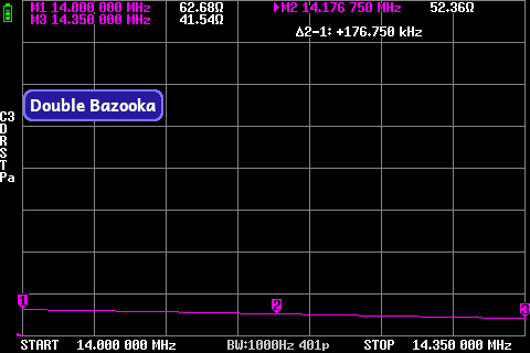
NanoVNA Sweeps
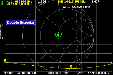
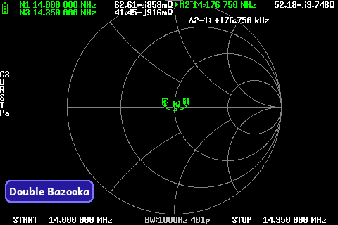
WOW! I was instantly blown away when I checked the Nano. No fiddling required. It was nearly perfect right out of the gate! It was 1.2:1 at it’s worst across the entire 20M band. Absolutely phenomenal performance.
WSPR
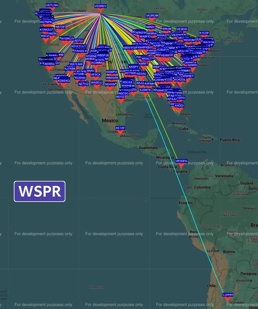
I ran my standard 1 Watt, 20 Minute WSPR test and the pattern is very nice and even.
Statistics:
Contacts: 317
SNR: Max: +06 Min: -34 Avg: -16
Distance: Max: 3343KM Min: 983KM Avg:1870

I let the WSPR test keeping going into greyline to check on the DX contacts. Unfortunately band conditions weren’t ideal. But it does show some DX promise.
10M Version
UPDATE: I built another one of these antennas for the 10M band. For this version, I decided to direct solder the coax feedline rather than use an SO-239 connector.
After soldering, I wrapped the connections with self amalgamating tape followed by electrical tape. For the center mount, I used a plastic light box cover. It’s ultralight and cheap. I used zipties to keep the coax in place. There’s quite a bit of weight on these connections with the RG-213 coax so having a bit of extra support is great.
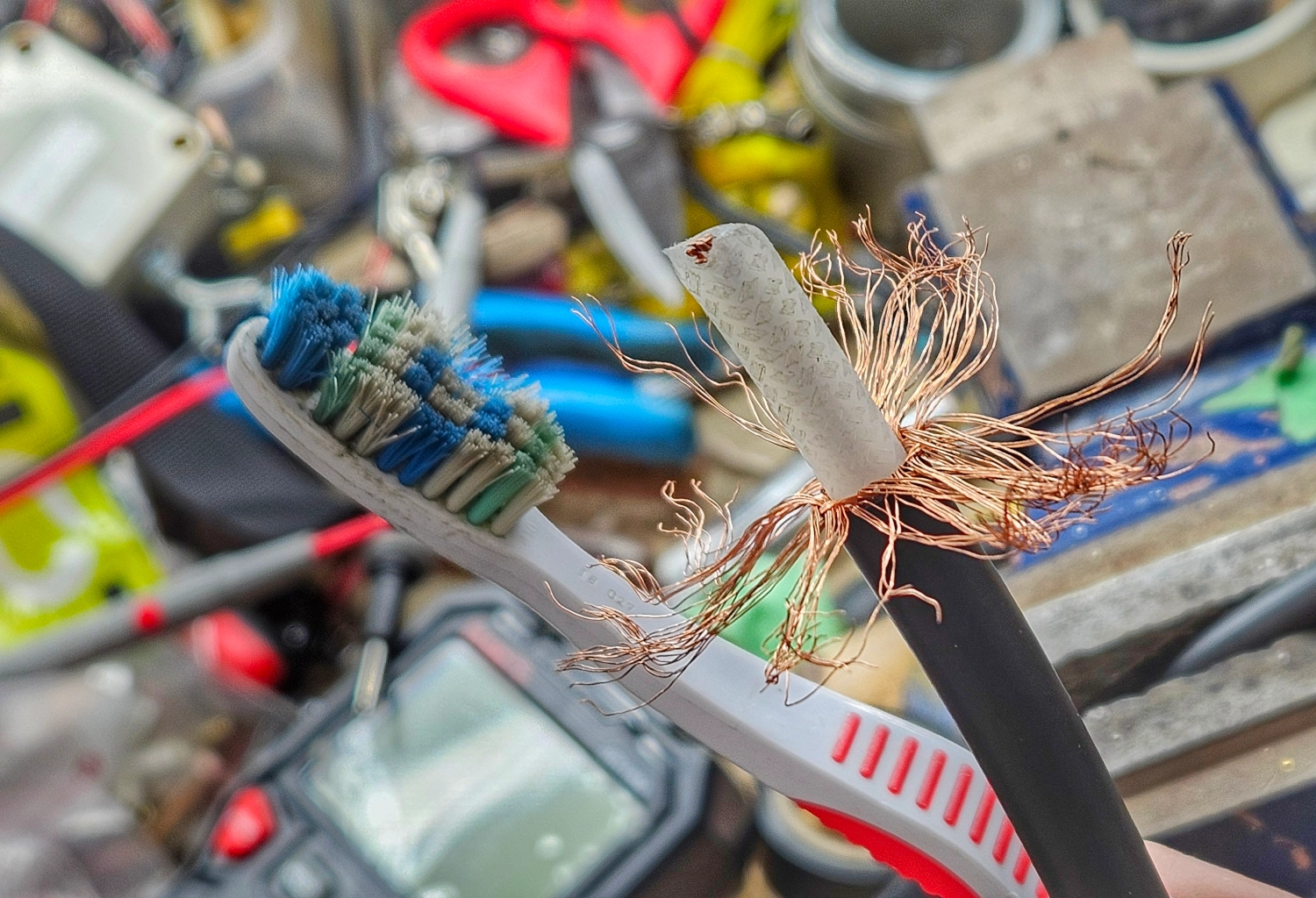
A really great coax tip is to use a tooth brush or a wire brush to separate the coax shield. I found that if I brushed the braid towards the cut end, the braid weave came right out easily. You are then left with nice straight coax shield.
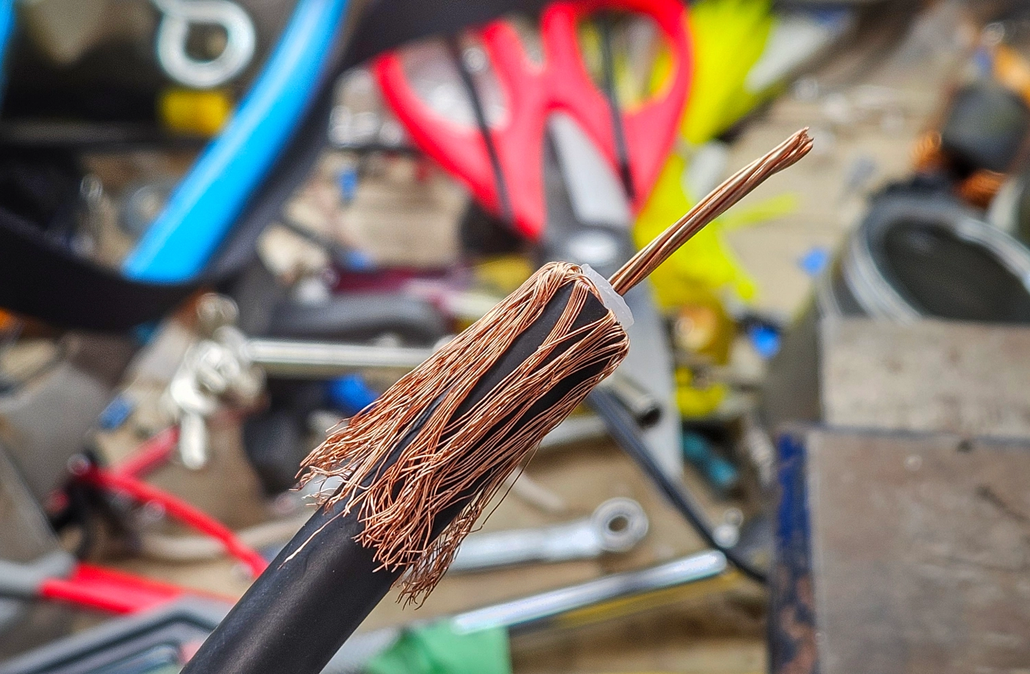
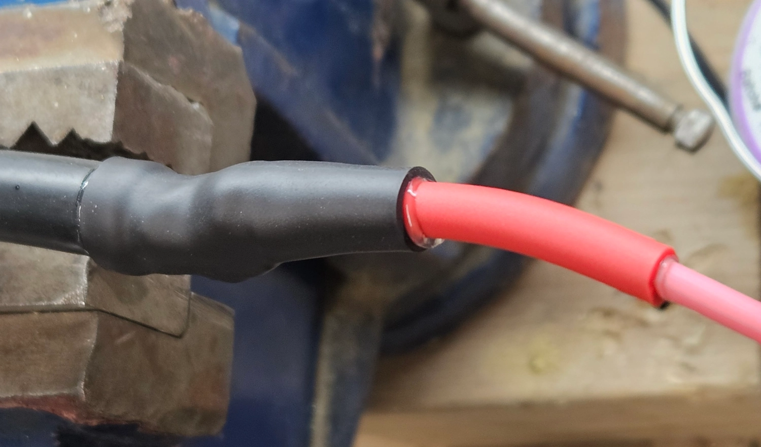
From there I soldered in the 14AWG pigtail and sealed it up with glue lined shrink wrap. This should be a water tight and extra strong connection.
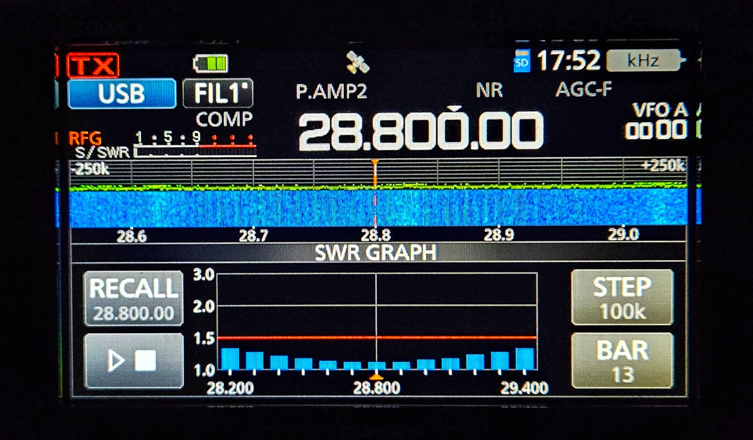
I set it up in the backyard for a quick test and wow! Again, the results were outstanding. To have this much of the 10M band under 1.5:1 SWR is really tremendous. This is from the IC-705 SWR meter.
Conclusion
The hype about this antenna is true! It’s an absolutely stunning performer. It is an incredibly quiet antenna too. My QTH is really noisy with power lines and RFI galore and this was an absolute pleasure to listen to. It was noticeably quieter than the OCFD on 20M. These kinds of antennas would make absolutely killer ragchew antennas on 40M & 80M. Highly recommended antennas!
73 de VE5REV