Battle of the Baluns
Something that has always intrigued me was the controversy about the ever so humble half wave dipole antenna. “Does a dipole need a balun?” And if so, what balun does it need?! YouTube influencer A says “Yes! You always need a balun!” Influencer B says “No you don’t! Son, just put that wire in the air!” Sad Ham A says “Dipoles are current fed! Using a voltage balun is the dumbest thing you could ever do!” Sad Ham B says “The voltage balun forces equal signals on both legs of the antenna which will have better results!” So, who is right?! And is there any actual data to back any of this up!? Enter: The Battle of the Baluns!

The Concept
The cornerstone of the argument stems from using coax with a dipole. You have an unbalanced feed line and a balanced antenna. There’s a mismatch there. 50Ω coax line and ~72Ω dipole center. Does this ~22Ω difference matter, other than a smidgeon of SWR? The answer is yes because of the introduction of everybody’s favourite boogey man, common mode current (CMC). The mismatch can result with the common mode current returning down the outside of the coax shield, back to the transmitter. It may bother you and it may not. But the other side of the coin is that the coax will start radiating such that the dipole becomes a tripole.
Hence the debate about the use of a balun to stop that CMC. But what balun should a ham use?
“Balun”
The term “Balun” has become a catch-all term so much so that it’s almost void of meaning entirely. We all know that it is a junction of “Bal“anced to “Un“balanced but it gets used interchangeably for Impedance Transformers and Chokes alike. So which of these is most appropriate to solve dipole antenna common mode current?
The Contenders
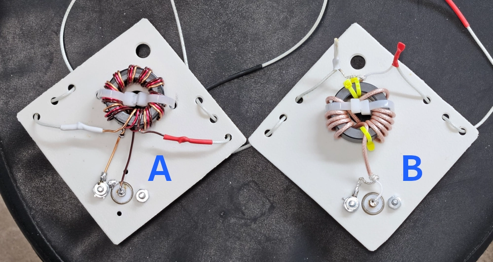
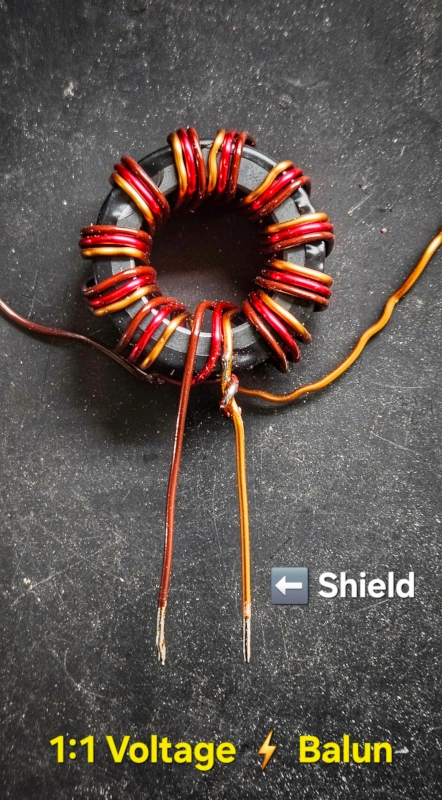
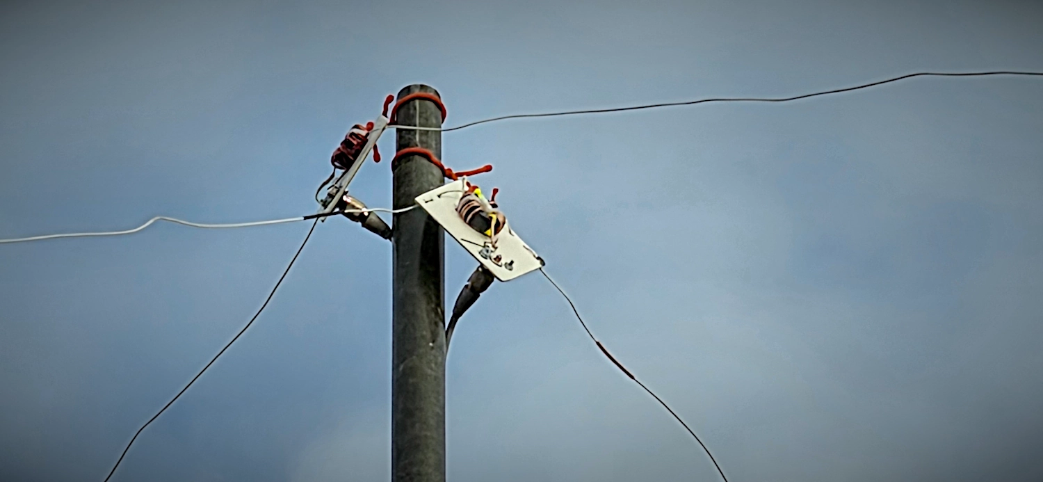
I built two, as identical as possible, 40M dipole antennas. Version A is a 1:1 Voltage Balun made with trifilar windings of 16AWG enamelled copper. Version B is a simple 1:1 Current Choke made with 12 turns of RG-316 coax. Both use FT140-43 cores (5943002701) with identical SO-239 connectors. The antenna radiators are directly soldered. Everything is mounted to plastic cutting board for strain relief. The wire is the magical aircraft cable our club salvaged. It’s probably 22 or 24AWG.
The Balun Build Notes
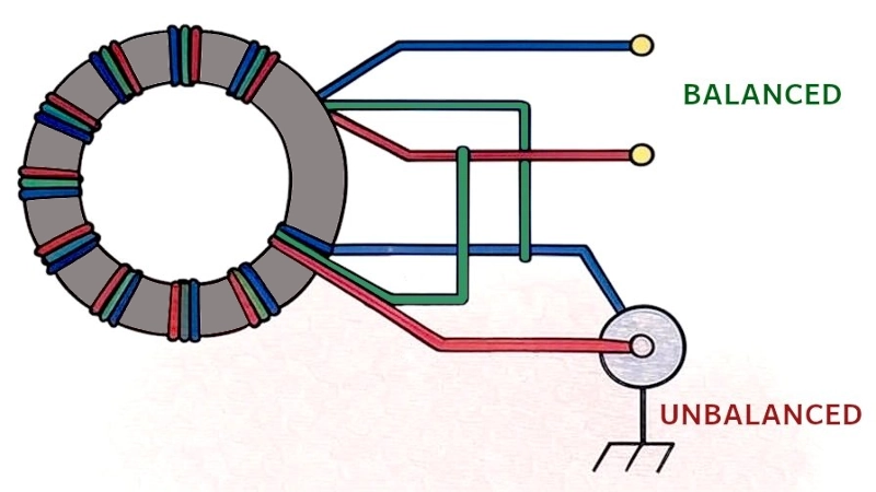
For the 1:1 Voltage Balun, unbalanced signal enters the transformer. The transformer splits this signal into two equal but out-of-phase components across the balanced outputs. This is achieved through the center-tapped winding, where the center tap is grounded, ensuring the voltages on the balanced side are equal in magnitude but opposite in phase.
The Experiment Concept and Details
I wanted to get some real-world testing data to find the winner. The trick is trying to devise a setup for fair comparison.
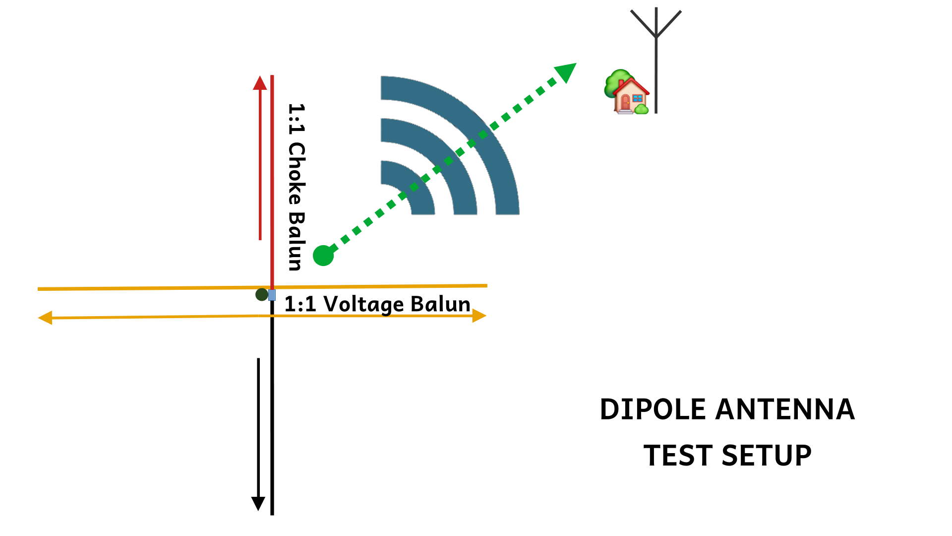
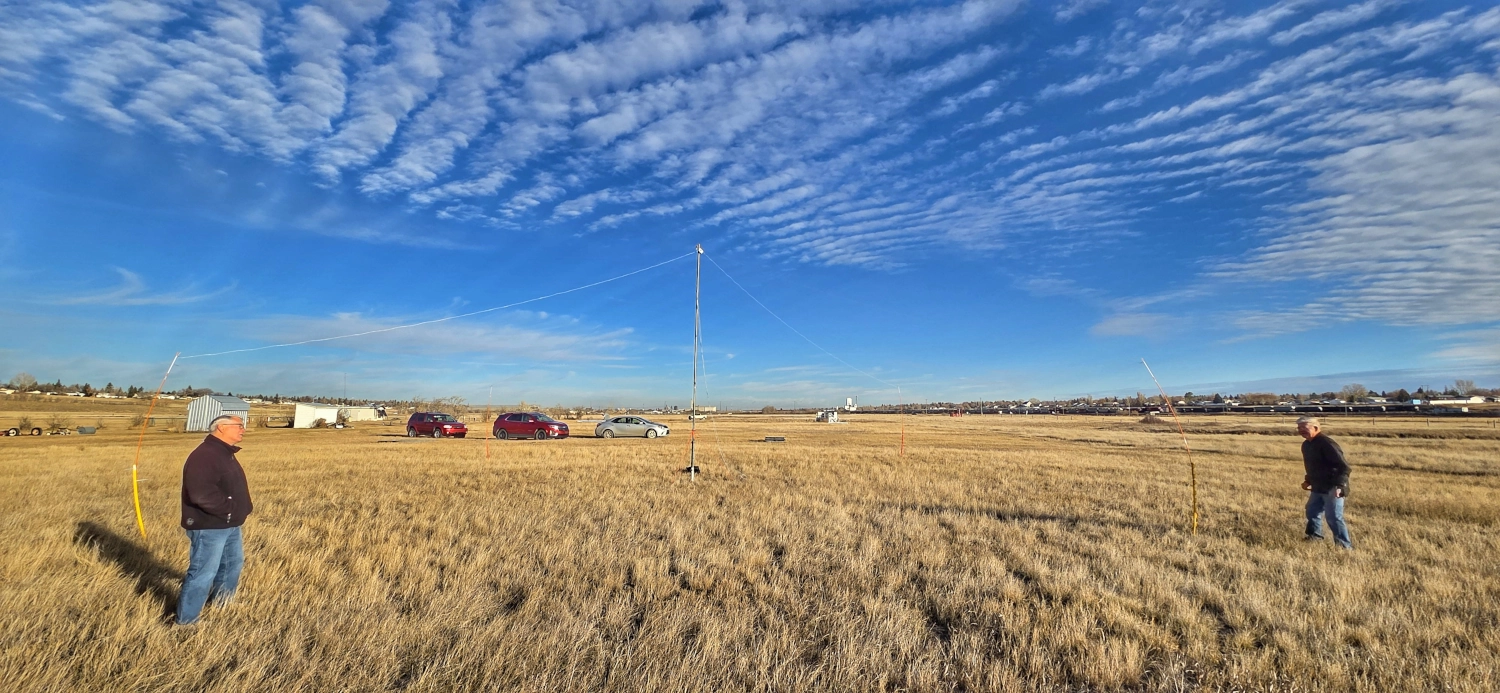
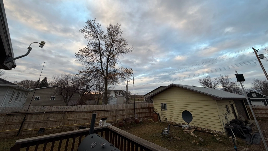
I elected to setup a single 20’ mast for NVIS deployment. The voltage balun antenna was deployed slightly higher than the current choke antenna (I flipped a coin on that), both perpendicular to each other (to hopefully minimize interaction). The receiving station was the vector direction between both antennas. The coax center of the current choke antenna (red in the diagram) was the end of the antenna facing the destination direction. The voltage antenna signal should be equal so it shouldn’t matter (all yellow in the diagram).
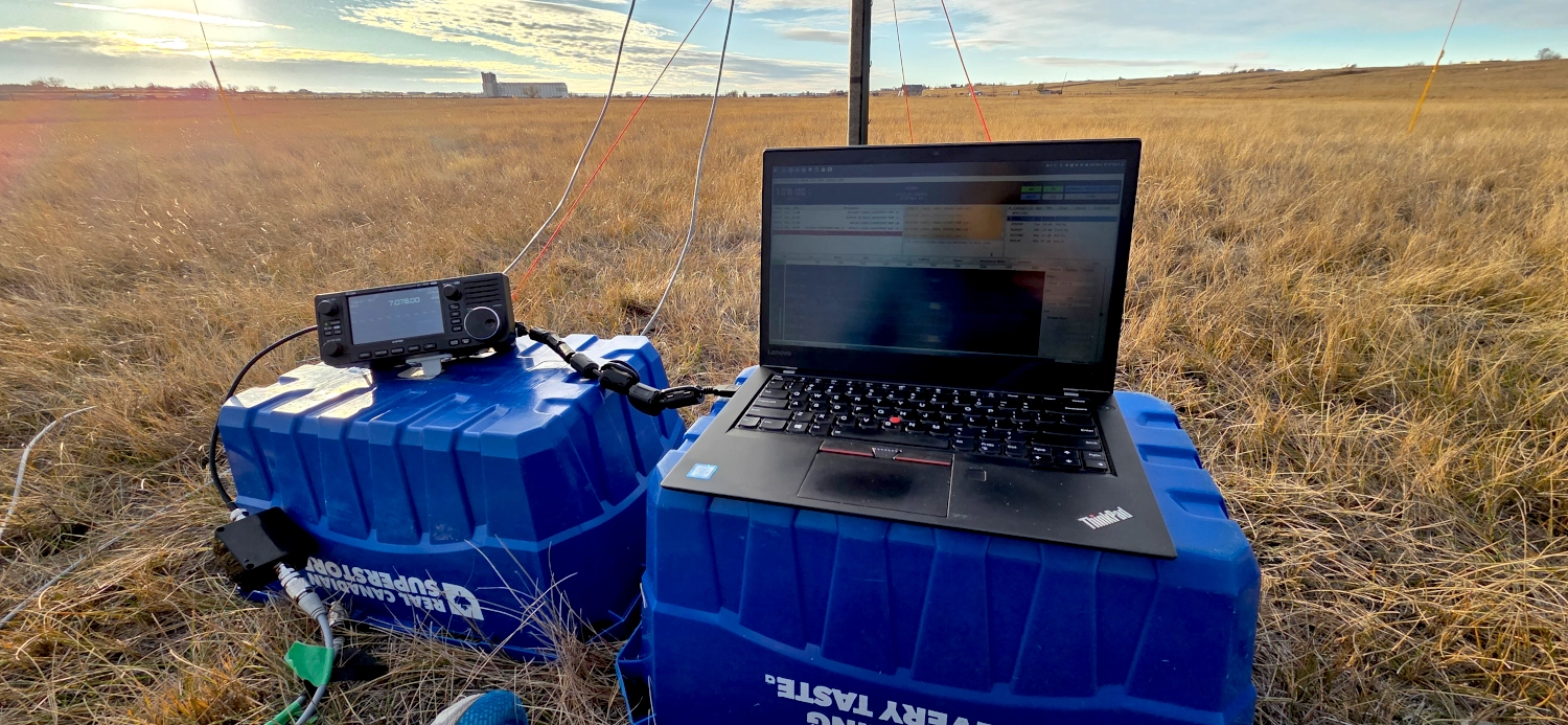
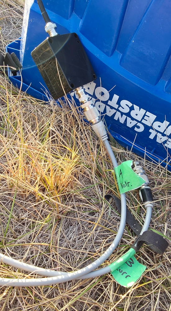
Each antenna was fed with an identical run of 25’ RG-8X coax. I put masking tape on each coax labelled with A and B to keep it straight. Both runs used an identical SO-239 to BNC adapter for connecting to the Icom IC-705 radio. There was a 1:1 current choke at the rig for the duration of all the tests. The legs of the radiators were held up with a plastic electric fence post and a fiberglass snow marker. The antenna wires were just tied onto the markers with zip ties. This put the end of legs up to about 8’ high. The testing itself was done with JS8Call. One antenna was connected to the radio and transmitted a 10 Watt transmission and the receiving station gave the SNR report in return. These numbers were recorded. The antennas were immediately swapped and a second transmission was done in succession with the alternating antenna. This way, the transmissions were as close as possible to normalize for conditions. I couldn’t devise a fairer approach than this.
Thanks to Crazy Chekov for this testing procedure. Check out his YouTube channel for his experiments that inspired this testing. And also, a huge thanks to Garvin, VE5ARV for access to the test location and helping setup the experiment.

The Receiving Station

I needed to find a station that was in the typical NVIS area from me. I put out a call on X.com and thankfully, Neil, N5EIL responded and said he could help. He was about 400km straight south of me in Montana. His antenna was a 44’ whip, 17’ off the ground. He was running 25 Watts on his end. Thanks again, Neil!
The Testing Data
Going into this test, my hypothesis was that the current choke version would come out on top as it would thwart common mode current better. However, check out the actual data.
The Voltage Balun was A
The Current Choke was B
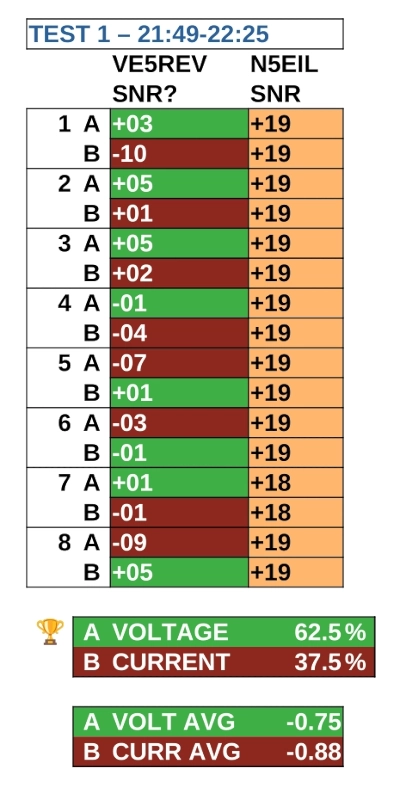
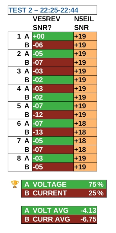
As you can see, the Voltage Balun was the undisputed champion of this test and it wasn’t even close. This corroborates Crazy Chekov’s results. The test I did was the only iteration of NVIS tests that he didn’t do. This seems to complete the overall picture and solidifies the most ideal configuration.
The Grand Result
I need to repeat this test in the future to further confirm the data. But from this testing session, the ideal dipole deployment configuration is: a 1:1 Voltage Balun in the center and a 1:1 choke at the rig.
Update: Round 2 Testing

73 de VE5REV