160M EFHW

The Top Band
The 160M Band is a bit of a holy grail in Ham Radio because it’s such a honkin’ huge antenna! Hardly anyone has the space needed to set one up. There’s lots of ‘compromised’ antenna versions out there to help get on the air on the top band. But one thing we have in VE5 land is space. We have lots and lots of space. So I figured we could build an EFHW version for Field Day. Well, we got and built the low-band triplexer and band pass filters so I thought we should have an antenna to operate with!
The Build
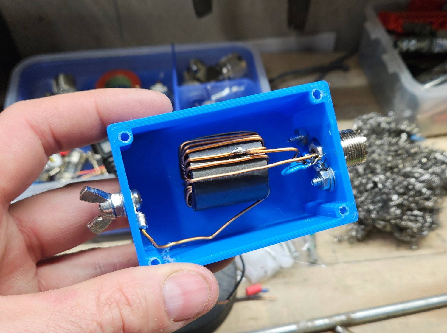
Transformer
From my previous experimentation, I found that for the lower bands, mounted close to the ground, they benefit from extra inductance. I built an 81:1 for a 40M NVIS antenna and had great results with it. So I figured I would start there for the 160M transformer build.
Type 61 Core: 2661102002 Size: 1.020” (25.91mm) OD.
120pF Capacitor
Enamel Wire, 2 primary & 18 secondary turns, auto-transformer style
3D Printed box for the housing
Wire
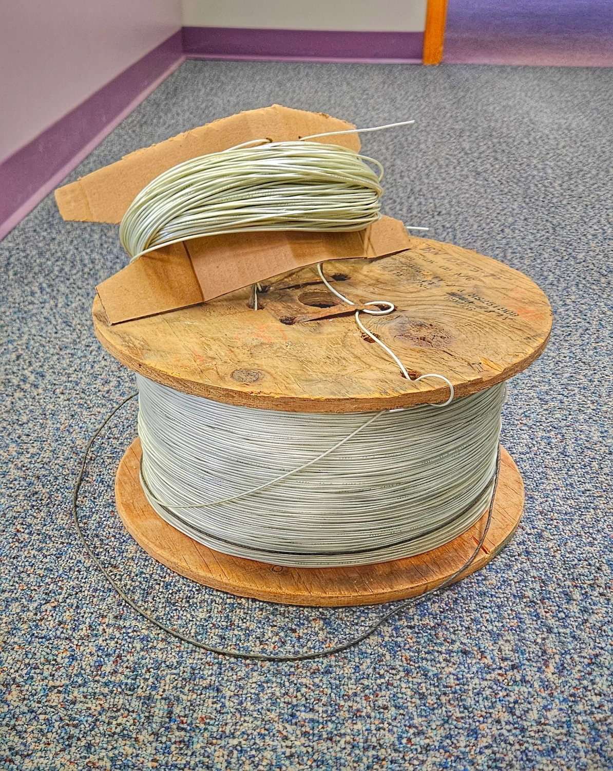
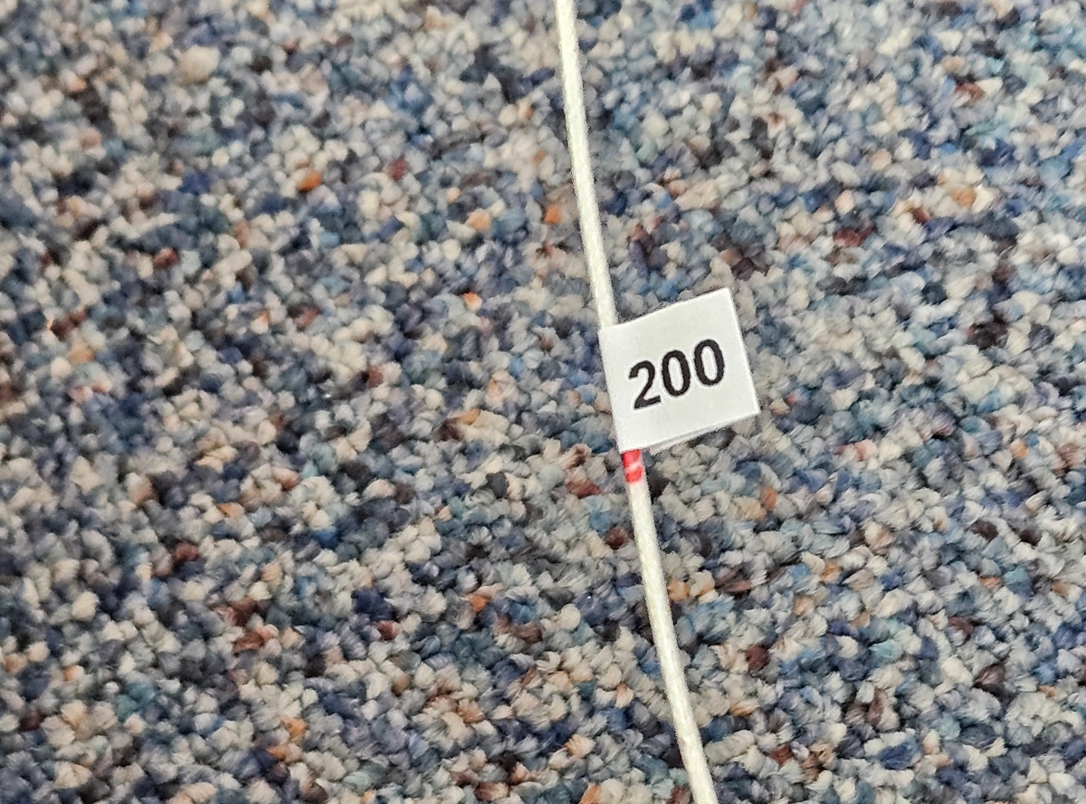
Our Club scored about 8 trillion feet of wire in a salvage operation. I think it’s 18AWG air craft cable or some such thing. All I know is there is a metric tonne of it and we can build wire antennas for the next 300 years and not run out! I measured out about ~270’ for the antenna and it didn’t even put a dent in the reel. Measuring this stuff was a nightmare. I measured 50’ at a time, marked it with red marker and put a little label tag on it so I knew where abouts I was in the measuring process.
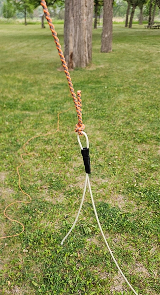
Counterpoise and Choke
My preferred counterpoise system for EFHW antennas is un-choked coax that is .05% of the full wavelength. So for 1.8MHz, my half wave is 260’ x 2 is 520. 520 x .05 is 26. I had a 25’ piece of coax in stock so I used it. It gets paired with a 1:1 choke on the rig side to isolate the radio from the counterpoise coax.
Deployment
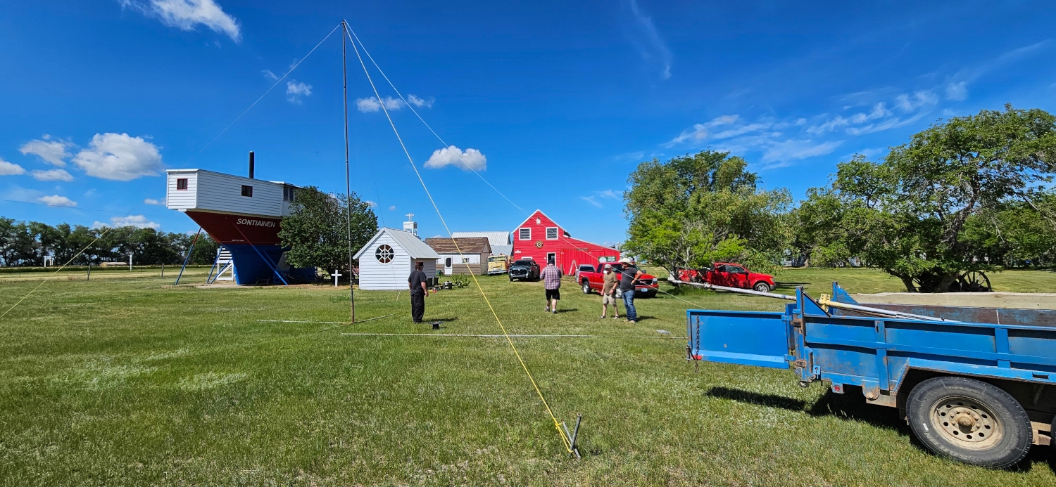
This is an absolutely beastly antenna! Everything I read suggested an inverted-L deployment. I knew there was going to be lots of weight on this wire just because there’s lots of it. I used my fibreglass military mast that is roughly 30’ tall and taped the wire to it with electrical tape for strain relief. Securing the mast and keeping it vertical was tricky with that much force pulling on the wire. Where I did the initial setup there was a gazebo. So I braced the heck out of the mast and stretched the wire out.
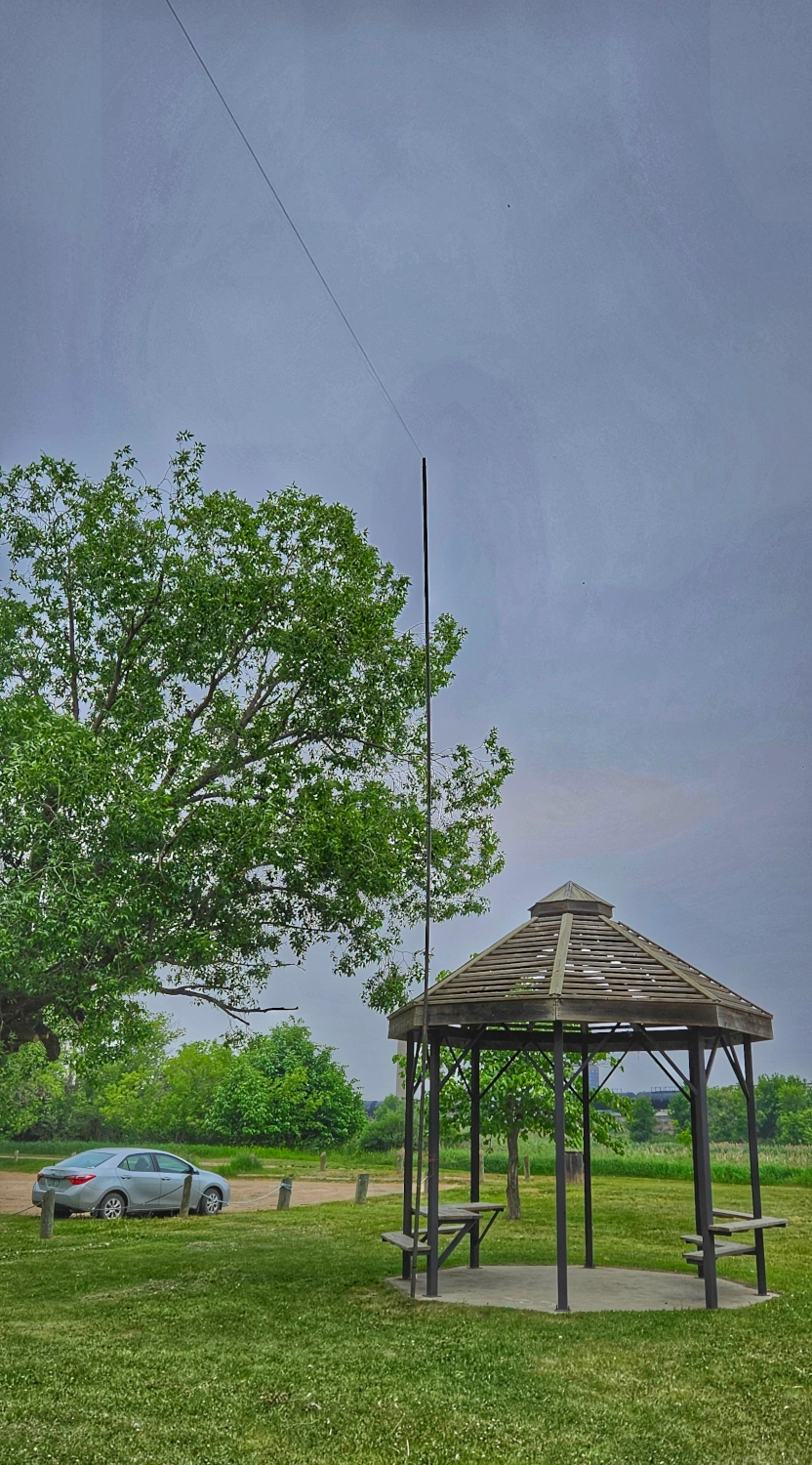
On the far end, I threw a line up over a tree branch and tied the paracord to the wire, securing the loop with some tape. I ended up having to cut the wire down to the 260’ mark in the tuning process but it was easy to lower the antenna wire down. I gently pulled the rope to raise up the wire and make it quasi-taught. Pro tip: you can never pull wire hard enough to make it flat so don’t even try.
Testing
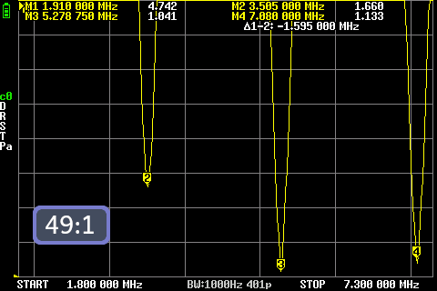
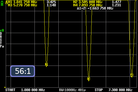
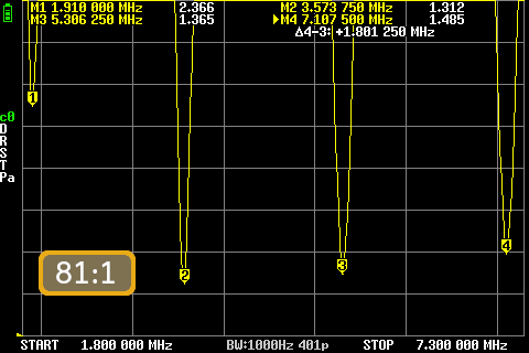
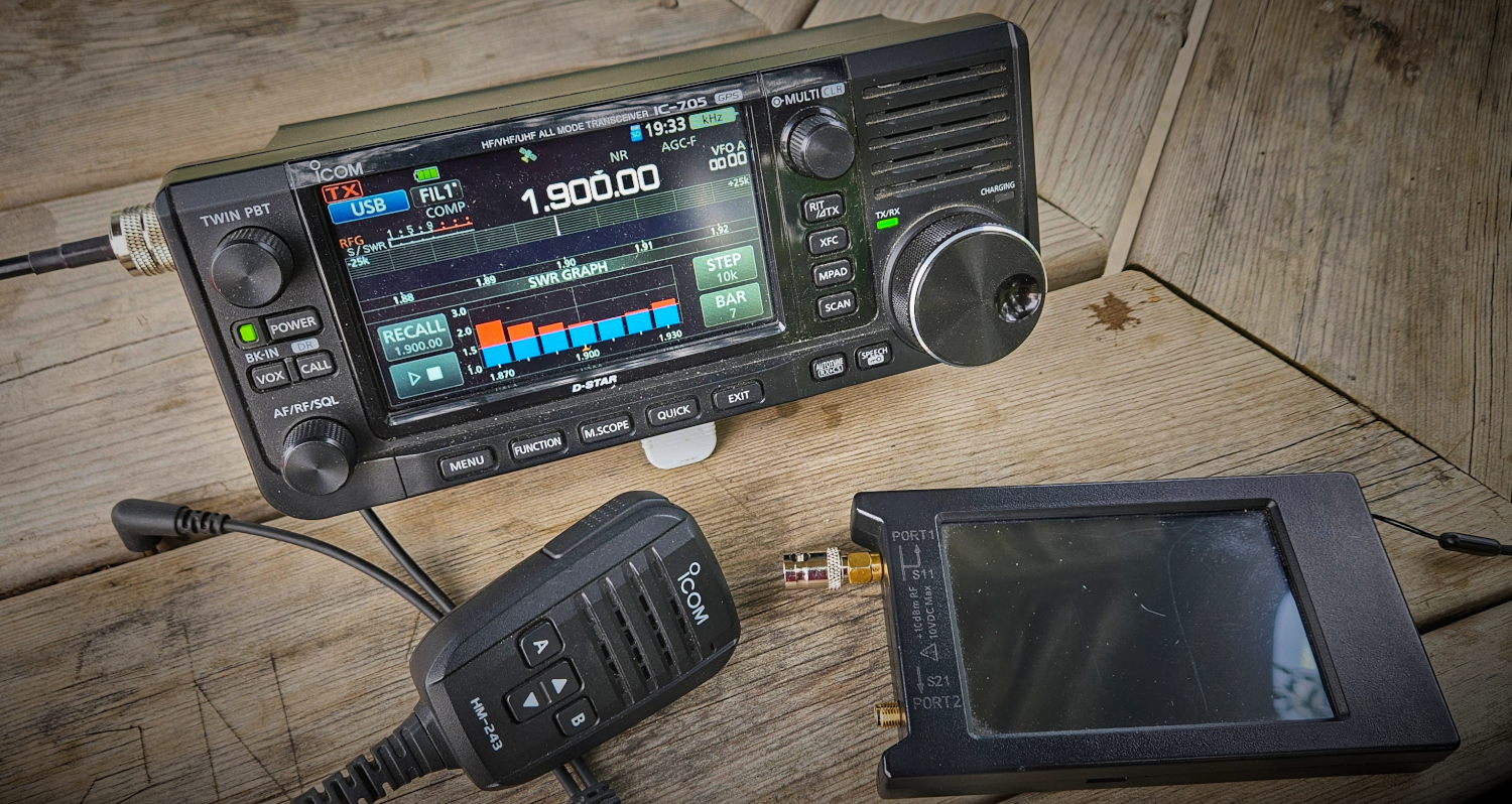
I brought 3 transformers with me for testing: 81:1, 56:1 and 49:1. My hunch was that the 81:1 was going to be the best choice (which it was) but it was very easy to swap out the other ones and check them with the NanoVNA.
49:1
56:1
81:1
Concluding Thoughts
My goal for this build was to get all of the low-bands under 3:1 SWR so an internal rig tuner could touch it up as needed. Mission accomplished! Again, the extra inductance of the 81:1 winding pattern brought the 160M band down into tunable territory. We will do some proper WSPR tests and such, probably at Summer Field Day. But now that we have unleashed the 160M Beast, it might be POTA time!
After Action Report
We deployed this bad boy at 2025 Summer Field Day. Thankfully, it cooperated and tuned up just fine with internal rig tuners as designed. It was a relatively “easy” deployment. We put the up the fibreglass mast and guyed it. Our club has the nifty ‘tip-up’ bases that make raising the masts a cinch.
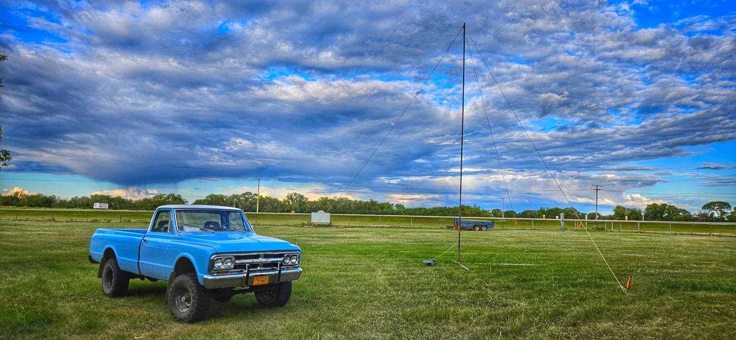
This is the 160M deployed beside VA5GAD’s classic 1967 C-10 for scale! This photo got lots of love when I posted it on X.
We had this antenna and a DX Commander for Field Day and this long wire was noticeably quieter by a lot. I operated it on 20M all day and made contacts from Alaska to Texas, Maryland to California and even picked up Montana which is an amazing feat in and of itself for 20M from our QTH! The only bummer was, band conditions were deplorable on both 160M and 80M! We made no contacts on 80M and 160M at all. So, it will be redeployed at Winter Field Day for another kick at the top band cat.
WSPR
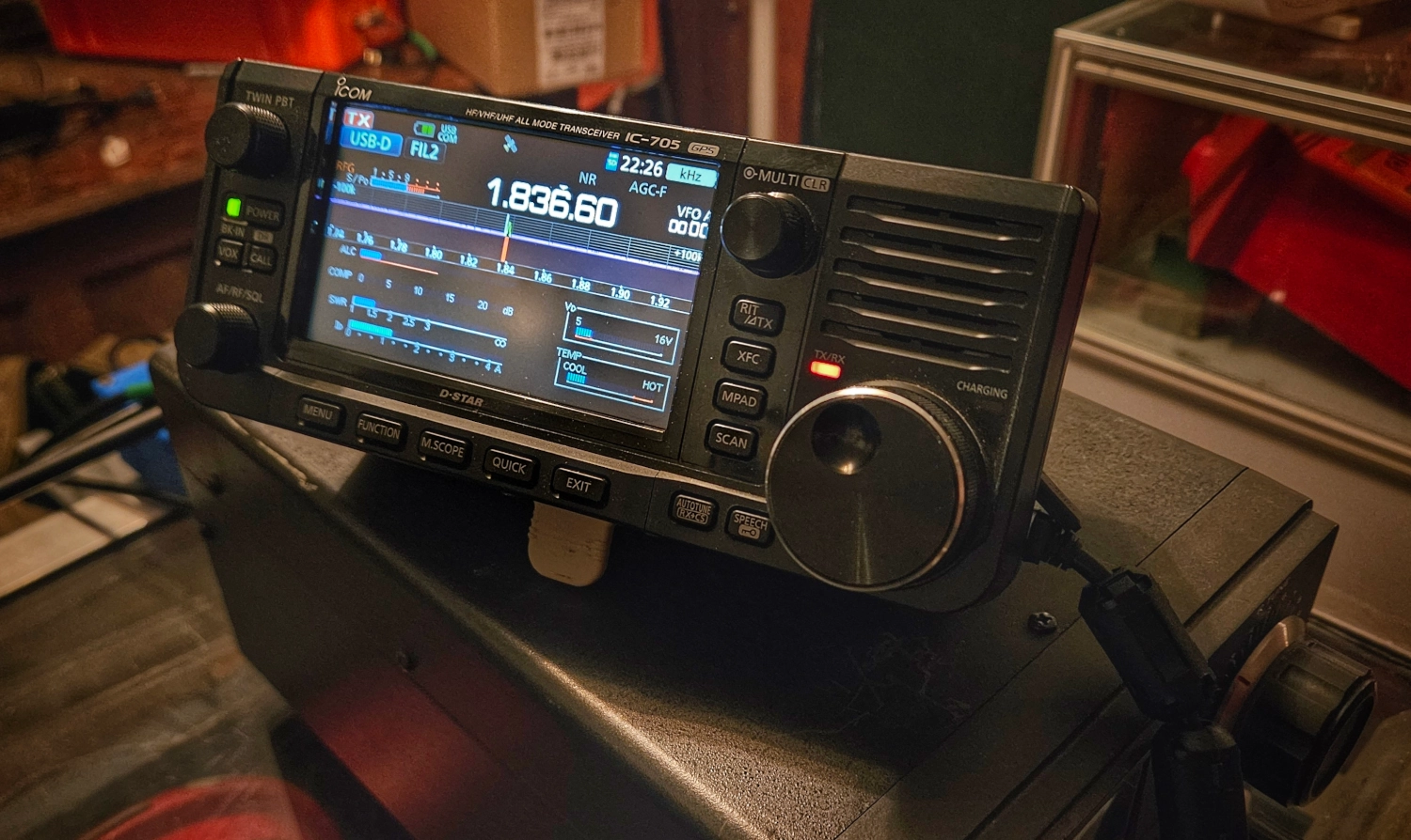
I took advantage of the poor operating conditions to run a WSPR test. The trusty IC-705 was run through a manual tuner and the best I could get was just over 1.5:1 SWR. I cranked it up to 2 watts to overcome the extra losses.
I ran the test for about 20 minutes or so and here’s the contacts map. It’s quite sparse but again, conditions were ultra-nasty. Shall re-run this test at Winter Field day and do a comparison.

73 de VE5REV